Eureka AIR delivers breakthrough ideas for toughest innovation challenges, trusted by R&D personnel around the world.

Wind turbine testing system

a wind turbine and testing system technology, applied in the direction of motors, structural/machine measurement, engine fuctions, etc., can solve the problems of transfer and insufficient to ensure the effect of transmission

Inactive Publication Date: 2010-10-26
VESTAS WIND SYST AS
View PDF10 Cites 16 Cited by
  • Summary
  • Abstract
  • Description
  • Claims
  • Application Information

AI Technical Summary

Benefits of technology

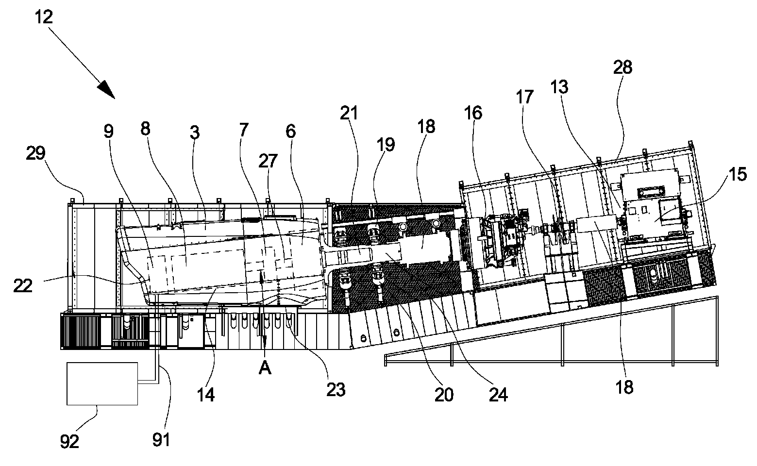
[0017]An advantageous feature of the invention is that the characteristics of a wind turbine system or at least part thereof may be tested in a broad physically simulated environment in the sense that wind resulting inputs and grid resulting inputs may be evaluated in combination, thereby providing a unique opportunity to incorporate feedback to and from the grid in a realistic situation or a certain desired test situation.
[0082]Performing the steps of the above mentioned method enables the skilled personnel performing the test to estimate in a reliable and reproducible way whether the wind turbine system meets a given set of specified requirements under different wind and grid conditions.

Problems solved by technology

A general challenge related to wind turbines is when wind turbines are coupled to weak utility grids.
A coupling to a weak grid may under some circumstances result in transfer of, e.g., transients, noise or voltage drops or peaks between the utility grid and a wind turbine coupled to the grid.
It is, however, not sufficient to make sure, that the electrical parts of the wind turbine system, such as the generator and the power frequency converter, are able to manage simulated grid conditions corresponding to what could be expected during operation of the wind turbine when they are tested as stand-alone units.

Method used


Image

  • Wind turbine testing system
  • Wind turbine testing system
  • Wind turbine testing system

Examples


Embodiment Construction

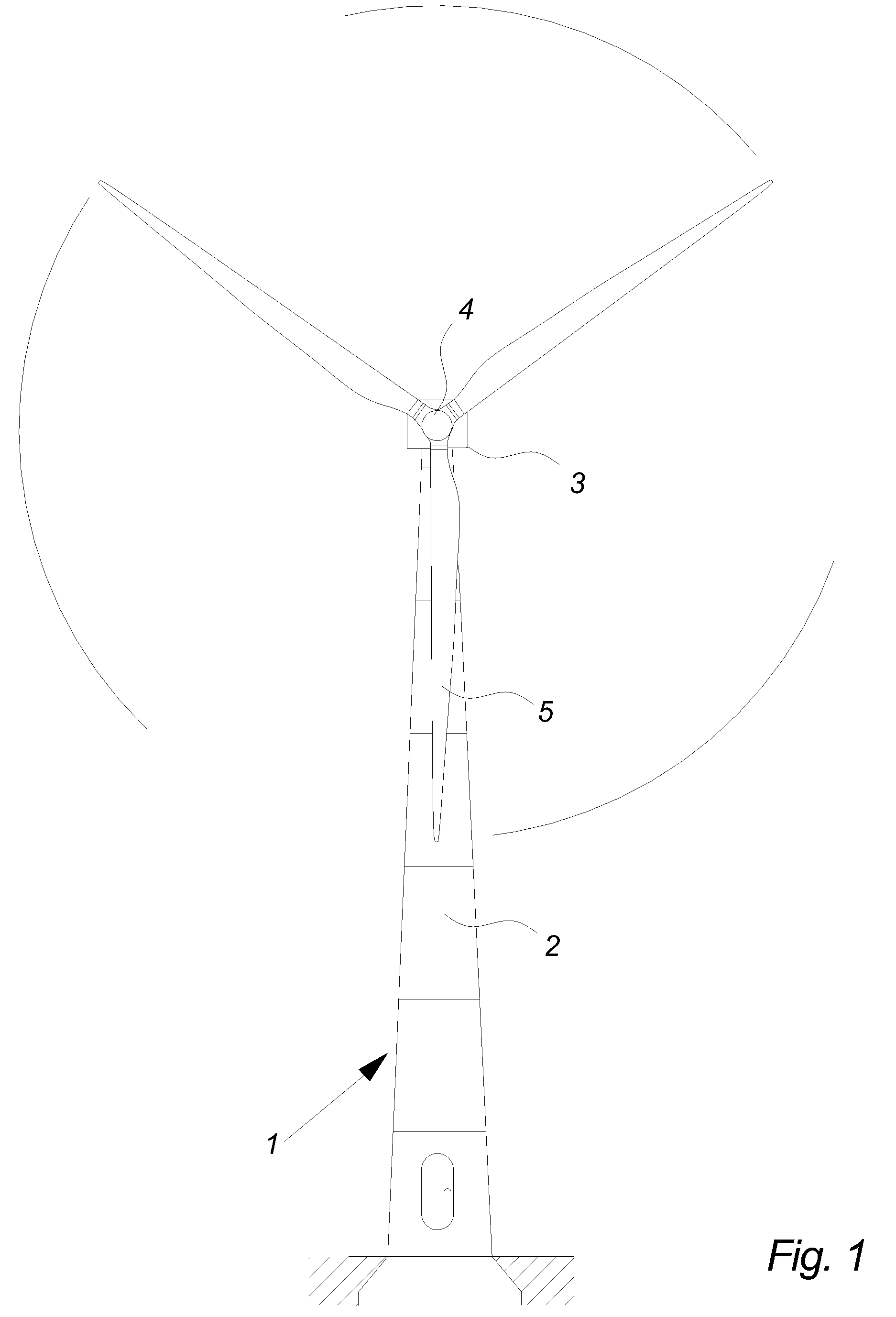
[0107]FIG. 1 illustrates a modern wind turbine 1 comprising a tower 2 placed on a foundation and a wind turbine nacelle 3 positioned on top of the tower 2. The wind turbine rotor 4, comprising three wind turbine blades 5, is connected to the nacelle 3 through the low speed shaft which extends out of the front of the nacelle 3.

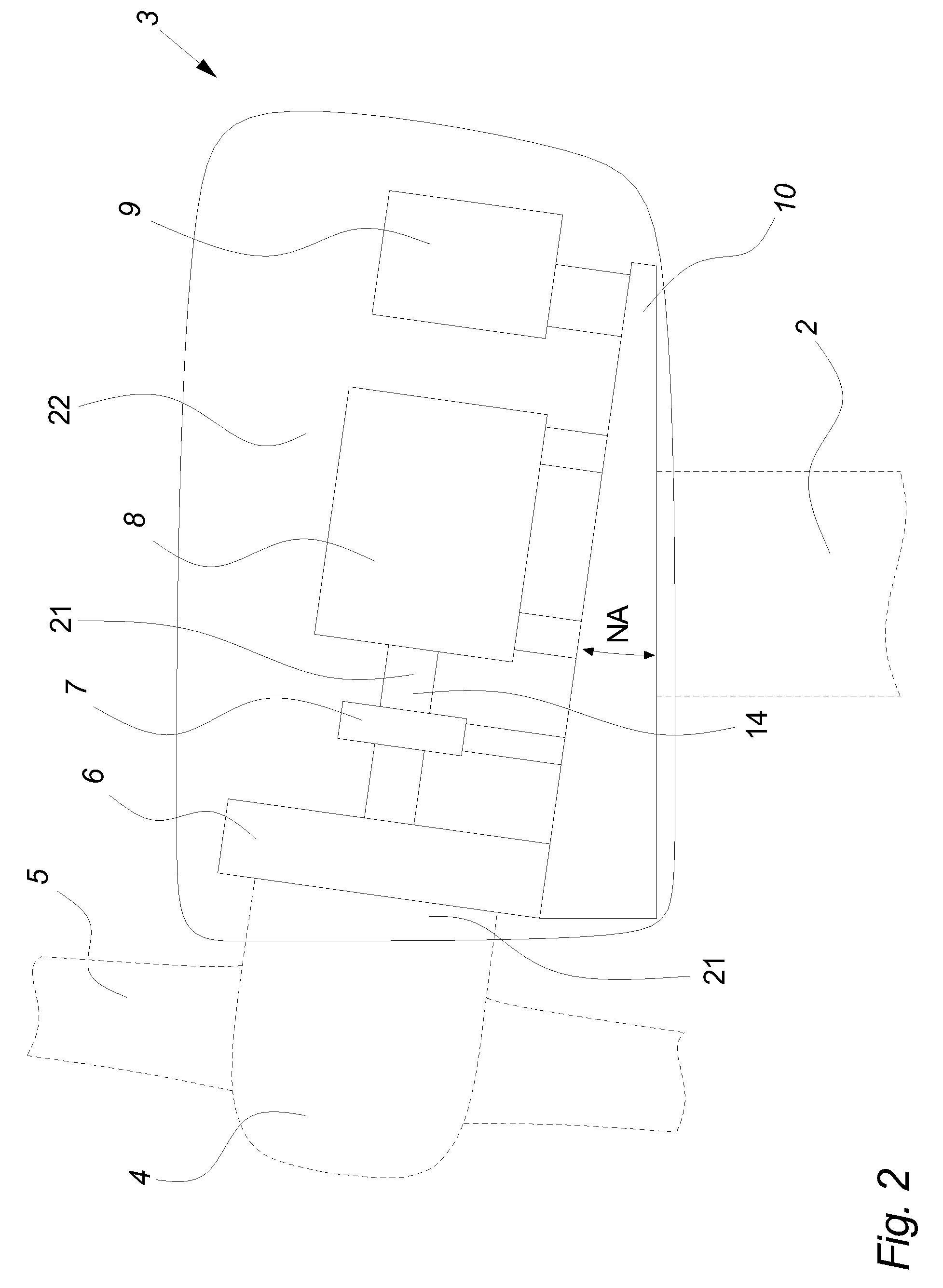
[0108]FIG. 2 illustrates a simplified cross section of a nacelle 3 as seen from the side. Nacelles 3 exist in a multitude of variations and configurations but in most cases the drive train 14 in the nacelle 3 comprises one or more of the following components: a gear 6, a coupling (not shown), some sort of braking system 7 and a generator 8. A nacelle 3 of a modern wind turbine 1 can also include a power frequency converter 9 (also called an inverter) and additional peripheral equipment such as further power handling equipment, control cabinets, hydraulic systems, cooling systems and more.

[0109]The weight of the entire nacelle 3 including the nacelle components ...


PUM

PropertyMeasurementUnit
voltageaaaaaaaaaa
voltageaaaaaaaaaa
voltageaaaaaaaaaa

Abstract

A wind turbine testing system is disclosed for testing at least a part of the nacelle components of a wind turbine system when mounted on a load carrying structure of a nacelle, said wind turbine testing system comprising a test bench being arranged to hold said load carrying structure including said nacelle components, a grid simulation system comprising a power converter system and a simulation controller being arranged to be electrically coupled to at least one of said nacelle components and being adapted for providing a simulated utility grid on the basis of a power supply and at least one control signal established by said simulation controller, and a wind simulation system comprising a wind turbine shaft rotating means arranged to be coupled to a rotating part of said generator system or a generator-related system of a nacelle or a part of a nacelle located in said test bench.

Description

CROSS-REFERENCE TO RELATED APPLICATIONS[0001]The present application is a continuation of pending International patent application PCT / DK2007 / 000337 filed on Jul. 3, 2007 which designates the United States and claims priority from Danish patent application PA 2006 00913 filed on Jul. 3, 2006, the content of which is incorporated herein by reference.FIELD OF THE INVENTION[0002]The invention relates to a wind turbine testing system for testing at least a part of the nacelle components of a wind turbine system.BACKGROUND OF THE INVENTION[0003]A general challenge related to wind turbines is when wind turbines are coupled to weak utility grids. A coupling to a weak grid may under some circumstances result in transfer of, e.g., transients, noise or voltage drops or peaks between the utility grid and a wind turbine coupled to the grid.[0004]Testing the individual parts of a wind turbine system for the capability of complying with different grid conditions before the wind turbine system is ...

Claims


Application Information

Patent Timeline
Patent Type & Authority Patents(United States)
IPC IPC(8): G01N3/02
CPCF03D1/003F05B2260/83G01R31/343Y02E10/726F03D80/50G01M5/005Y02E10/72
Inventor BISGAARD, JAN
Owner VESTAS WIND SYST AS
Why Eureka
Eureka Blog
Learn More