System and method for liquid air production, power storage and power release

a technology of liquid air production and power storage, applied in emergency power supply arrangements, magnetic bodies, machines/engines, etc., can solve the problems of increasing complexity and capital costs, unable to achieve the effect of increasing energy output and energy efficiency

Inactive Publication Date: 2010-10-26
EXPANSION ENERGY
View PDF29 Cites 24 Cited by
  • Summary
  • Abstract
  • Description
  • Claims
  • Application Information

AI Technical Summary

Benefits of technology

[0008]The present invention, in its many embodiments, alleviates to a great extent the disadvantages of known power storage systems by converting energy to liquid air (L-Air) for power storage and release and using the L-Air and ambient air for heat exchange purposes. All of the cold from released L-Air is recovered by a working loop of air for greater energy output. Embodiments of the present invention provide energy efficient storage, replacement and release capabilities by cooling and warming air through heat exchange, recovering both heat and cold from the system, storing energy as liquid air and pumping liquid air to pressure to release energy.
[0010]The air is directed out the exit of the cold flue assembly. Then the air is compressed and the heat of compression recovered from the compressed air. Preferably, compression of the air includes two-stages of compression where the air is first compressed to a first pressure at this stage of the cycle and the heat of compression recovered from the compressed air. The recovered heat of compression from the compressed air may be directed to an absorption chiller to drive the absorption chiller. The absorption chiller is fluidly connected to the cold flue assembly. Refrigerant may be directed from the absorption chiller to the cold flue assembly to help cool the inlet air entering the cold flue assembly. The remaining moisture and carbon dioxide (CO2) are removed from the air by adsorption, preferably using a molecular sieve assembly.
[0012]A vapor portion of the substantially liquefied air in the storage apparatus, or “flash air” may be directed to the main heat exchanger, and recovered cold from the vapor portion used to further cool the inlet air flowing in. This vapor portion would thus be warmed by the inlet air. The vapor portion is further warmed, preferably to approximately 220° F. and specifically by the heat of compression recovered from elsewhere in the process. The warmed vapor portion of the substantially liquefied air is directed to the molecular sieve assembly so that the substantially liquefied air removes the carbon dioxide and moisture that had been collected there. The warm sweep air, which is still at nearly the 70 psia pressure at which it left the storage tank as flash air, moves on to a generator-loaded hot-gas expander, producing power that is used on-site to run some of the instruments, valves, pumps and other such devices, and thus improving the relationship between the total amount of power delivered for storage to the system and the amount of L-Air that results from that power. (This is called “sweeping” the molecular sieve assembly; thus, the warmed vapor portion of the substantially liquefied air directed to the molecular sieve assembly is also referred to as “sweep air” herein.).

Problems solved by technology

It should be noted that the compression could be performed in a single stage with some loss of efficiency or in three or more stages with efficiency gains but increased complexity and capital costs.

Method used


Image

  • System and method for liquid air production, power storage and power release
  • System and method for liquid air production, power storage and power release
  • System and method for liquid air production, power storage and power release

Examples


Embodiment Construction

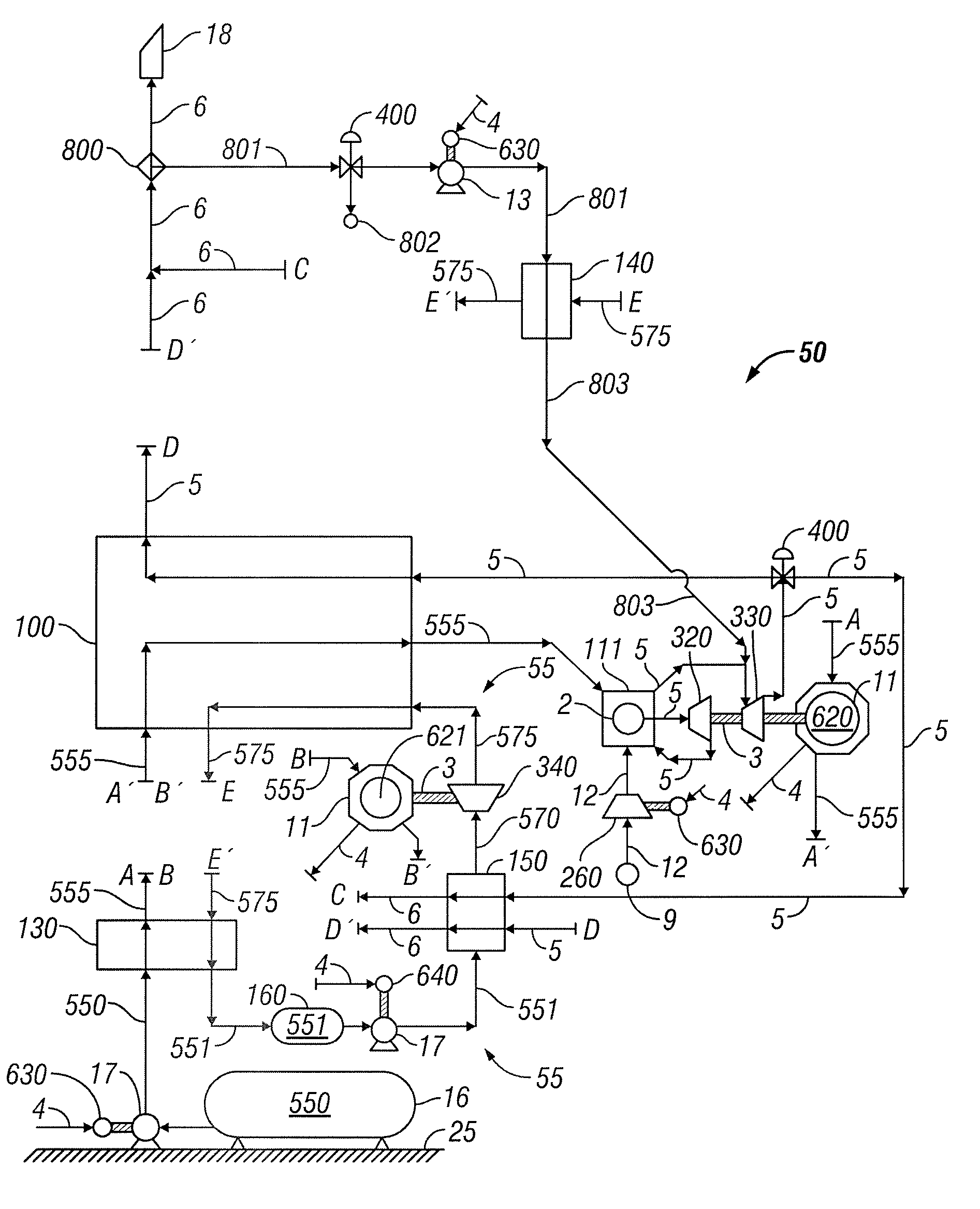
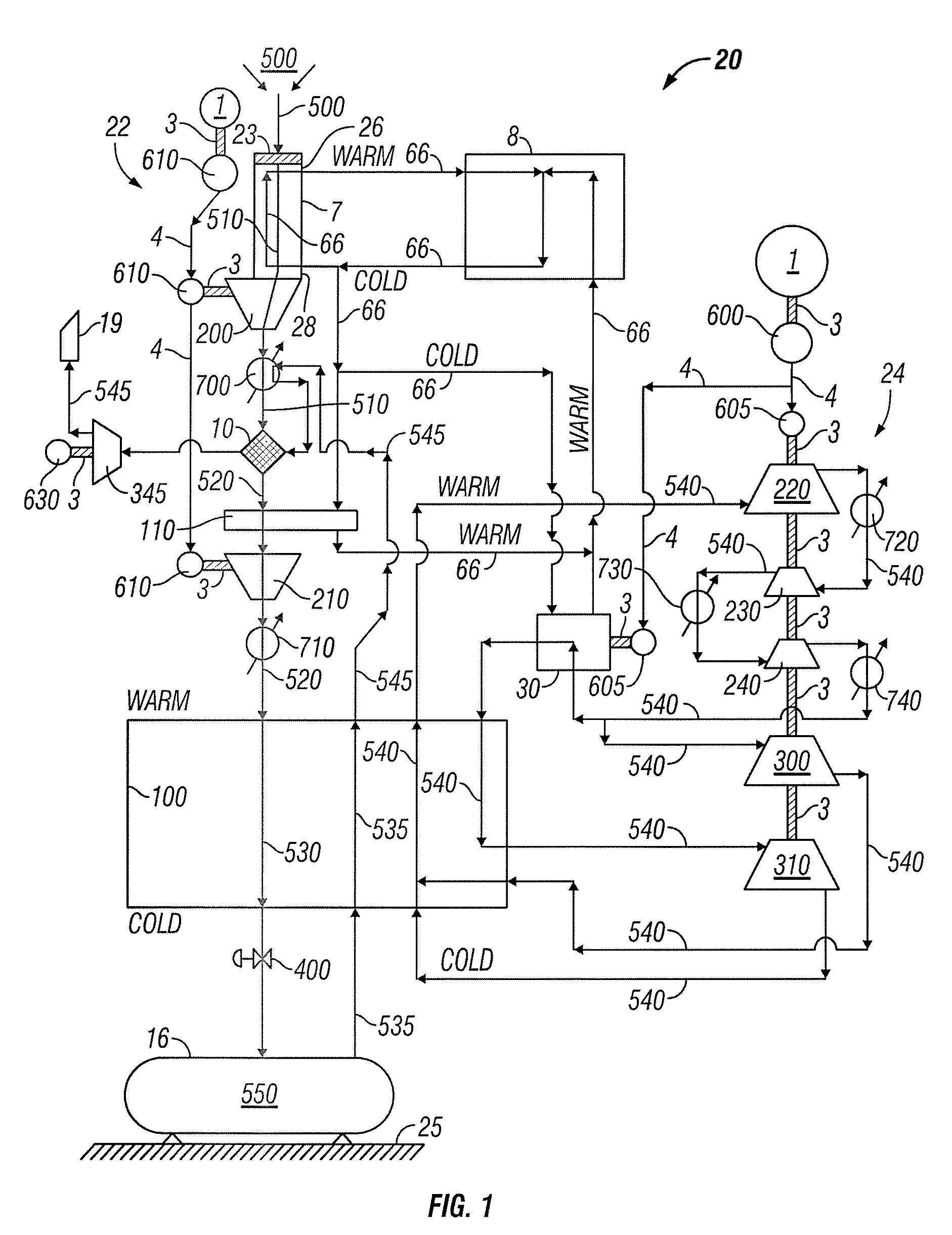
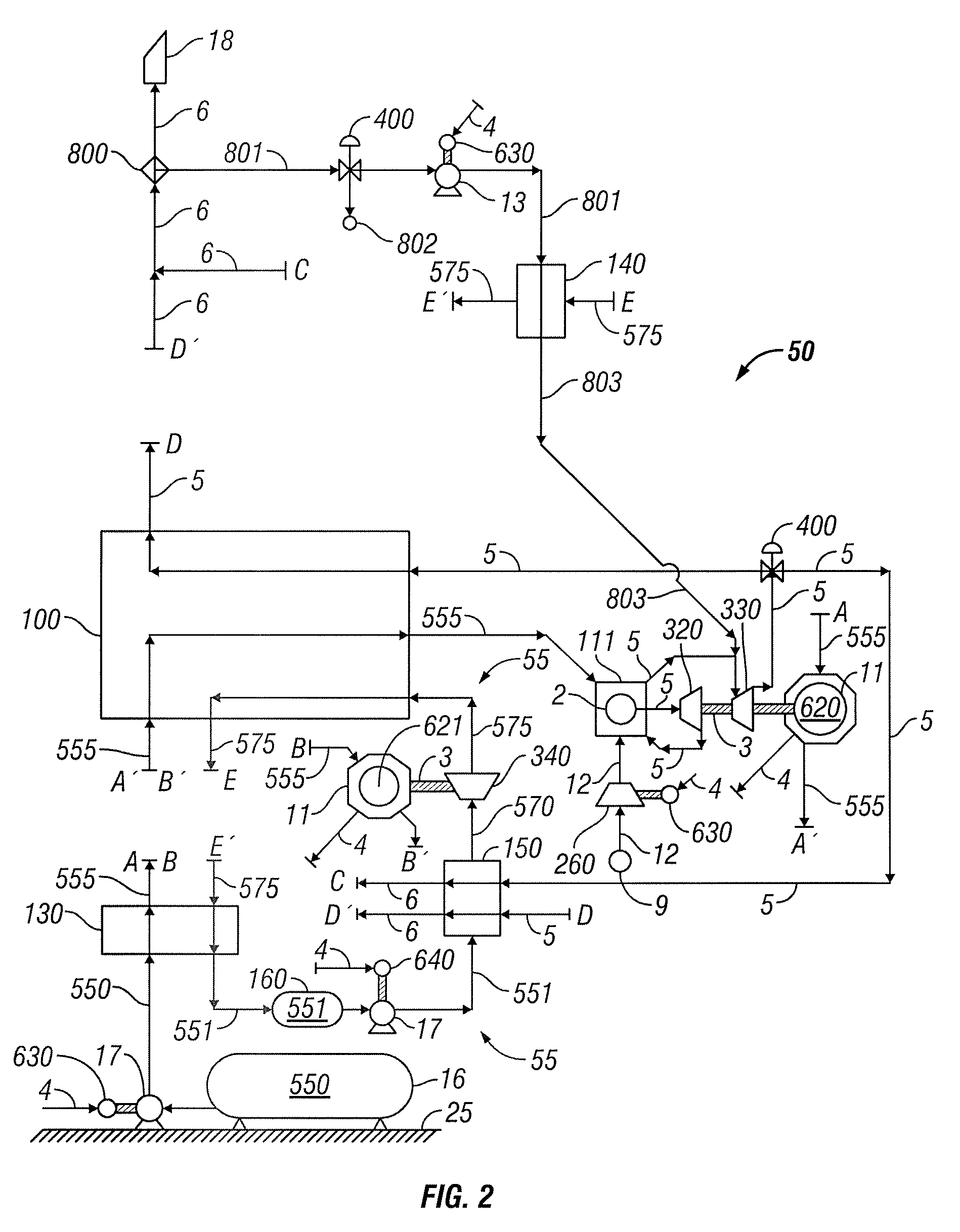
[0027]In the following paragraphs, embodiments of the present invention will be described in detail by way of example with reference to the accompanying drawings, which are not drawn to scale, and the illustrated components are not necessarily drawn proportionately to one another. Throughout this description, the embodiments and examples shown should be considered as exemplars, rather than as limitations on the present invention. As used herein, the “present invention” refers to any one of the embodiments of the invention described herein, and any equivalents. Furthermore, reference to various aspects of the invention throughout this document does not mean that all claimed embodiments or methods must include the referenced aspects. Reference to temperature, pressure, density and other parameters should be considered as representative and illustrative of the capabilities of embodiments of the invention, and embodiments can operate with a wide variety of such parameters.

[0028]Referrin...


PUM


Abstract

Systems and methods for storing and releasing energy comprising directing inlet air into a vertical cold flue assembly, a portion of moisture being removed from the air within the cold flue assembly. The air is directed out of the cold flue assembly and compressed. The remaining moisture is substantially removed and the carbon dioxide is removed from the air by adsorption. The air is cooled in a main heat exchanger such that it is substantially liquefied using refrigerant loop air, The substantially liquefied air is directed to a storage apparatus. The refrigerant loop air is cooled by a mechanical chiller and by a plurality of refrigerant loop air expanders. In energy release mode, working loop air warms the released liquid air such that the released liquid air is substantially vaporized, and the released liquid air cools the working loop air such that the working loop air is substantially liquefied. A portion of the released liquid air is directed to the at least one generator and used as bearing air for the at least one generator. The substantially vaporized air is directed to a combustion chamber and combusted with a fuel stream. Combustion gas may be directed from the combustion chamber to at least one expander, the expanded combustion gas split into two portions. The first portion may be directed to a first heat exchanger, and the second portion may be directed to a second heat exchanger such that the second portion heats and substantially vaporizes the released liquid air.

Description

CROSS-REFERENCE TO RELATED APPLICATIONS[0001]This application is a continuation-in-part of U.S. patent application Ser. No. 12 / 127,520, filed on May 27, 2008, which is incorporated herein by reference in its entirety.FIELD OF THE INVENTION[0002]The present invention relates to power storage and release systems and methods.BACKGROUND OF THE INVENTION[0003]Wind power is desirable because it is renewable and typically cleaner than fossil fuel power sources. Wind turbines capture and convert the energy of moving air to electric power. However, they do so unpredictably and often during low power demand periods when the value of electric power is substantially lower than during peak demand periods. Without a way to achieve certainty of delivery during peak demand periods (also known as “firm” power), and without a way to store low-value off-peak power for release during high-value peak periods, the growth of wind power and other intermittent renewable power sources may be constrained, kee...

Claims


Application Information

Patent Timeline
Patent Type & Authority Patents(United States)
IPC IPC(8): F25J1/00
CPCF01D15/005F02C6/14F25J1/0012F25J1/004F25J1/0045F25J1/005F25J1/007F25J1/0204F25J1/0227F25J1/0242F25J1/0251F25J1/0268F25J1/0284F25J1/0288F05B2220/61F25J2205/66F25J2230/02F25J2230/04F25J2230/22F25J2230/30F25J2235/02F25J2240/80F25J2240/90F25J2245/40F25J2260/30F25J2270/16F25J2270/906F28D2021/0033Y02E70/10Y02E20/16Y02E60/36F25J2230/20Y02E10/72F25J1/00F25J3/02
Inventor VANDOR, DAVID
Owner EXPANSION ENERGY
Why Eureka
Try Eureka