Piezoelectric transformer type ionizer and neutralization method

a technology of ionizer and piezoelectric transformer, which is applied in the direction of generator/motor, plasma technique, electrostatic charge, etc., can solve the problems of deterioration of neutralizing performance, metal particles scattering, and high probability of local deterioration of top end, so as to prolong maintenance interval, simplify maintenance work, and high accuracy of neutralization

Active Publication Date: 2010-10-26
SMC CORP
View PDF3 Cites 23 Cited by
  • Summary
  • Abstract
  • Description
  • Claims
  • Application Information

AI Technical Summary

Benefits of technology

[0004]It is an object of the present invention to provide a piezoelectric transformer type ionizer and a neutralization method using the piezoelectric transformer for overcoming the disadvantage of the generally employed ionizer using the piezoelectric transformer, that is, the needle electrode which causes the local deterioration and scattering of the metal particles to deteriorate the neutralizing performance in a short period such that highly accurate neutralization is maintained for a long period to prolong the maintenance interval and to simplify the maintenance work while holding an ion balance in good condition.
[0013]The present invention provides an ionizer capable of maintaining a highly accurate neutralization for a long period using the piezoelectric transformer, and prolonging the maintenance interval and simplifying the maintenance work while holding the ion balance in a good condition, and a neutralization method using the ionizer.

Problems solved by technology

In the ionizer using the piezoelectric transformer, as the electric field is focused onto a top end of the needle electrode to generate ions, the top end is likely to be locally deteriorated.
This may cause metal particles to scatter, and as a result, the neutralizing performance becomes deteriorated in a short period.

Method used


Image

  • Piezoelectric transformer type ionizer and neutralization method
  • Piezoelectric transformer type ionizer and neutralization method
  • Piezoelectric transformer type ionizer and neutralization method

Examples


embodiment

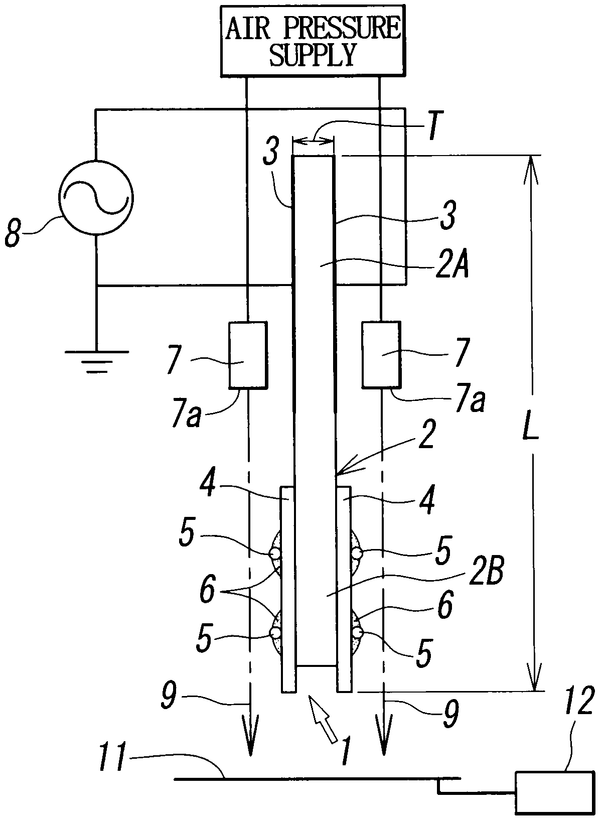
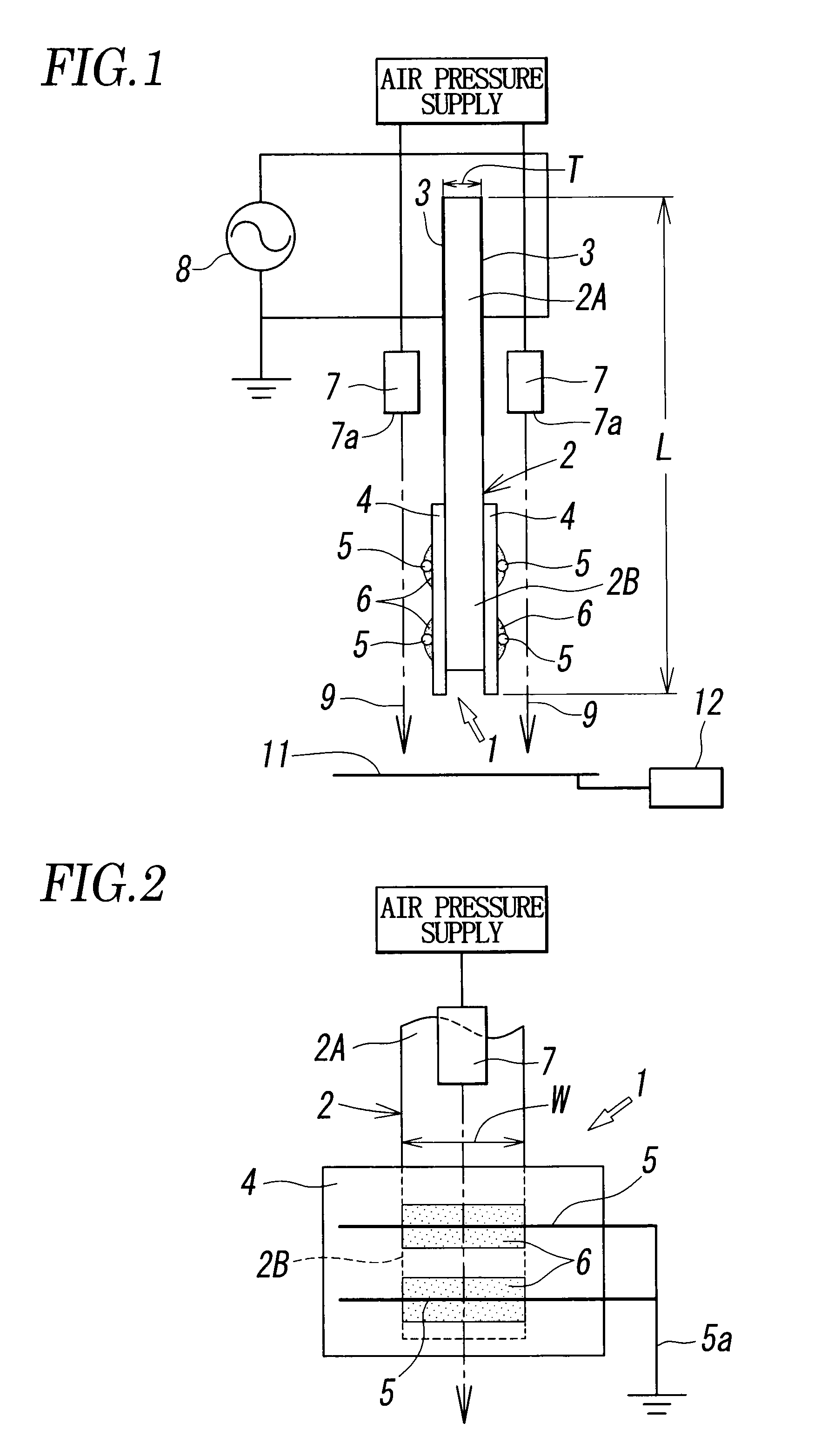
[0032]A thin rectangular solid shaped PZT piezoelectric transformer of Rosen type with length of 50 mm, width of 13 mm, and thickness of 2 mm was used as the piezoelectric transformer 1 as shown in FIGS. 1 and 2. Metal vapor deposition was performed on both upper and lower surfaces of the primary section 2A of the piezoelectric transformer 1 to form the electrode 3. Meanwhile, a polyimide film with thickness of 175 μm was applied to the upper and the lower surfaces of the secondary section 2B for insulation. Two tungsten wires each with the radius of 100 μm were adhered onto the polyimide film toward a width W direction as the equipotential direction to form the ground electrode 5 for grounding ends of all the wires. The resonance frequency standard value of the PZT piezoelectric transformer was as low as 33 kHz.

[0033]Two air nozzles 7 connected to the compressor were disposed to allow the compressed air to flow along the upper and lower surfaces of the secondary section 2B of the p...


PUM


Abstract

With a piezoelectric transformer formed of a ferroelectric element which generates a high voltage in a secondary section upon application of an AC voltage to a primary section, ground electrodes are attached to upper and lower surfaces of the secondary section of the piezoelectric transformer via a dielectric sheet for insulation in tight contact therewith such that a dielectric barrier discharge occurs around the ground electrodes to generate positive and negative ions, and an air flow is injected from an air nozzle to flow toward a neutralized subject across the ground electrodes.

Description

TECHNICAL FIELD[0001]The present invention relates to an ionizer for neutralizing electrostatically charged works using a piezoelectric transformer, and a neutralization method using the ionizer.BACKGROUND ART[0002]An ionizer which allows a piezoelectric transformer to generate a high voltage so as to be applied to a needle electrode for generating ions has been known as disclosed in Patent Document 1, Japanese Unexamined Patent Application Publication No. 10-302994. The ionizer is operated using the high voltage generated at a secondary section of the piezoelectric transformer upon application of AC low voltage to a primary section thereof. As disclosed in Patent Document 1, the high voltage generated in the secondary section (output side) is applied to a needle electrode for generating ions.[0003]In the ionizer using the piezoelectric transformer, as the electric field is focused onto a top end of the needle electrode to generate ions, the top end is likely to be locally deteriora...

Claims


Application Information

Patent Timeline
Patent Type & Authority Patents(United States)
IPC IPC(8): H05F3/00
CPCH01T23/00H05H1/24H05H1/2481H05F3/04
Inventor YASUOKA, KOICHISHIBATA, YUKIFUJIWARA, NOBUHIROSUZUKI, SATOSHISATO, TOSHIO
Owner SMC CORP
Why Eureka
Try Eureka