Two-stage decompression ejector and refrigeration cycle device

a decompression ejector and cycle device technology, applied in the direction of refrigeration components, machines/engines, lighting and heating apparatus, etc., can solve the problem of increasing the noise level nl

Inactive Publication Date: 2010-11-02
DENSO CORP
View PDF3 Cites 12 Cited by
  • Summary
  • Abstract
  • Description
  • Claims
  • Application Information

AI Technical Summary

Benefits of technology

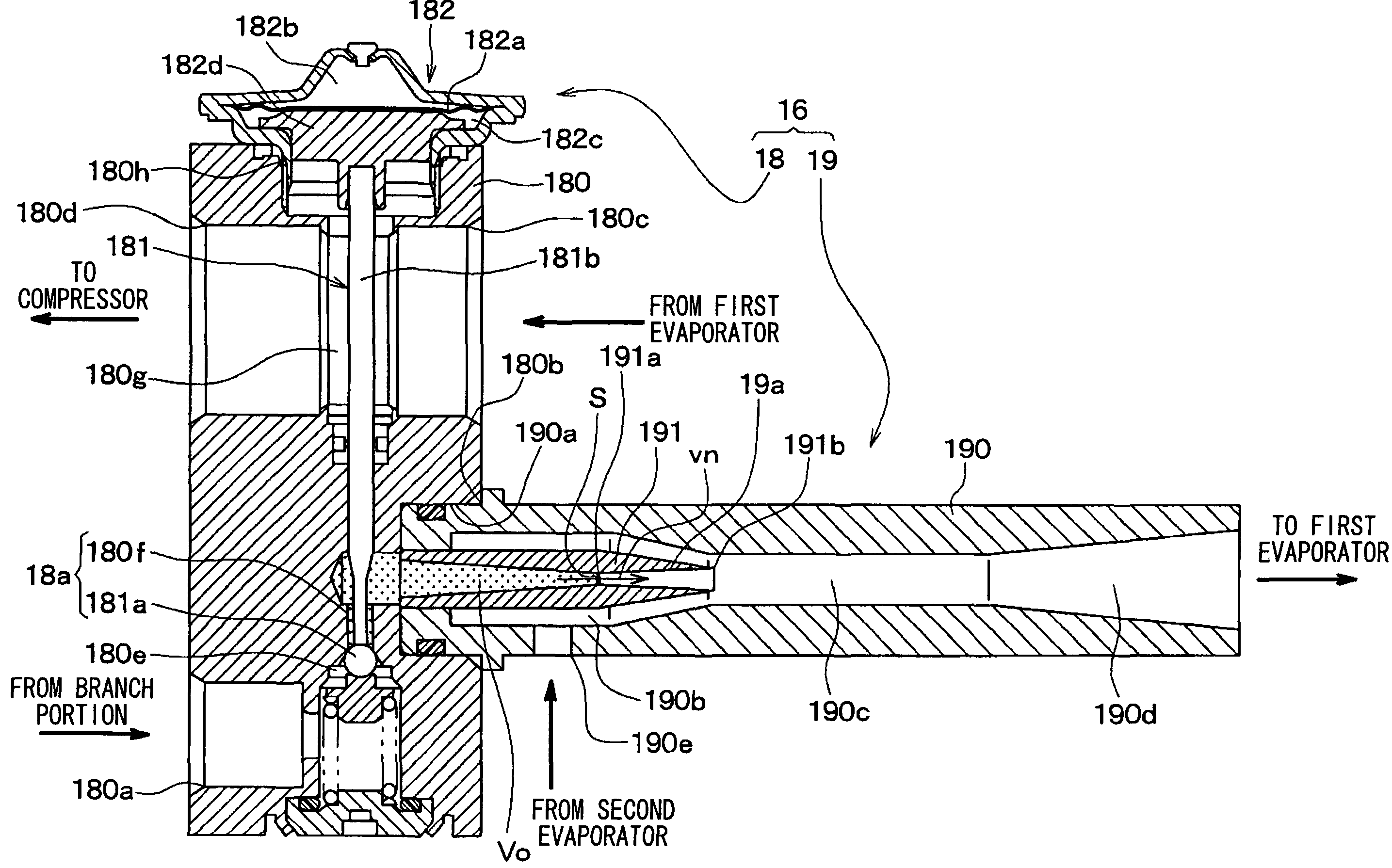
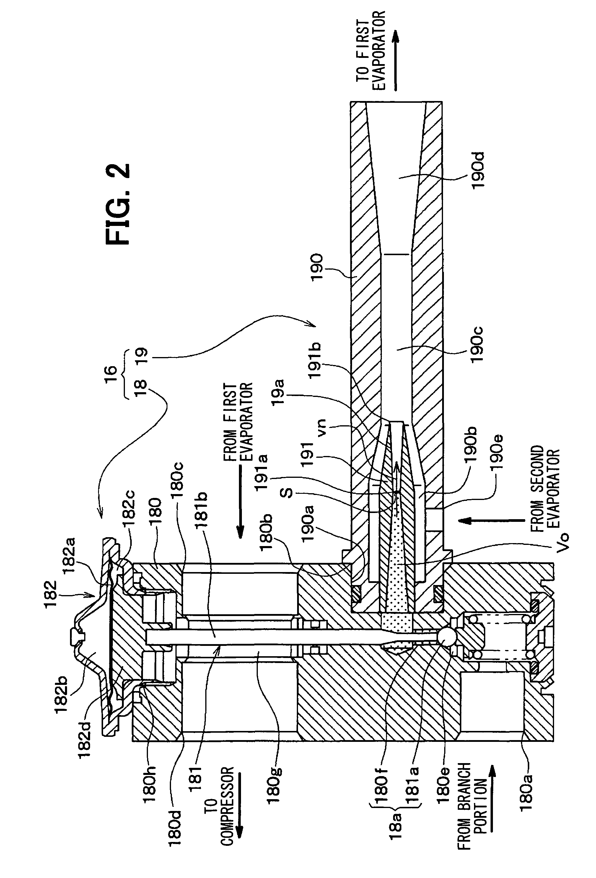
[0021]As shown in FIG. 11, the pressure pulsation of the intermediate-pressure refrigerant is reduced with increasing Vo×S / vn thereby to decrease an amount of increase in pressure at the diffuser. In particular, when Vo×S / vn≧0.07, the pressure pulsation of the intermediate pressure is effectively reduced. In contrast, the increase in pressure is reduced due to reduction or extinction of air bubbles (boiling nuclei) existing in the intermediate-pressure space, thereby reducing an ejector efficiency. When Vo×S / vn≦0.7, it can prevent the amount of increase in pressure from greatly decreasing.
[0024]Because Vo×S / vn≧0.07, it can suppress the low-frequency abnormal noise generated at the two-stage decompression ejector on startup of the cycle when the two-stage decompression ejector is applied to a refrigeration cycle device. Additionally, when Vo×S / vn≦0.7, it can prevent the drastic reduction in the ejector efficiency, thereby preventing the COP from being reduced.
[0026]Thus, the first throttle passage and the second throttle passage can be formed in the one nozzle, and thereby it is possible to make the two-stage decompression ejector compact.
[0027]Alternatively, the variable throttle mechanism may include a throttle passage of a thermal expansion valve, and a valve body. Accordingly, the two-stage decompression ejector can be achieved, for example, by a simple structure in which a box type thermal expansion valve is integrally connected to the ejector whose minimum refrigerant passage area of the nozzle is not changed.
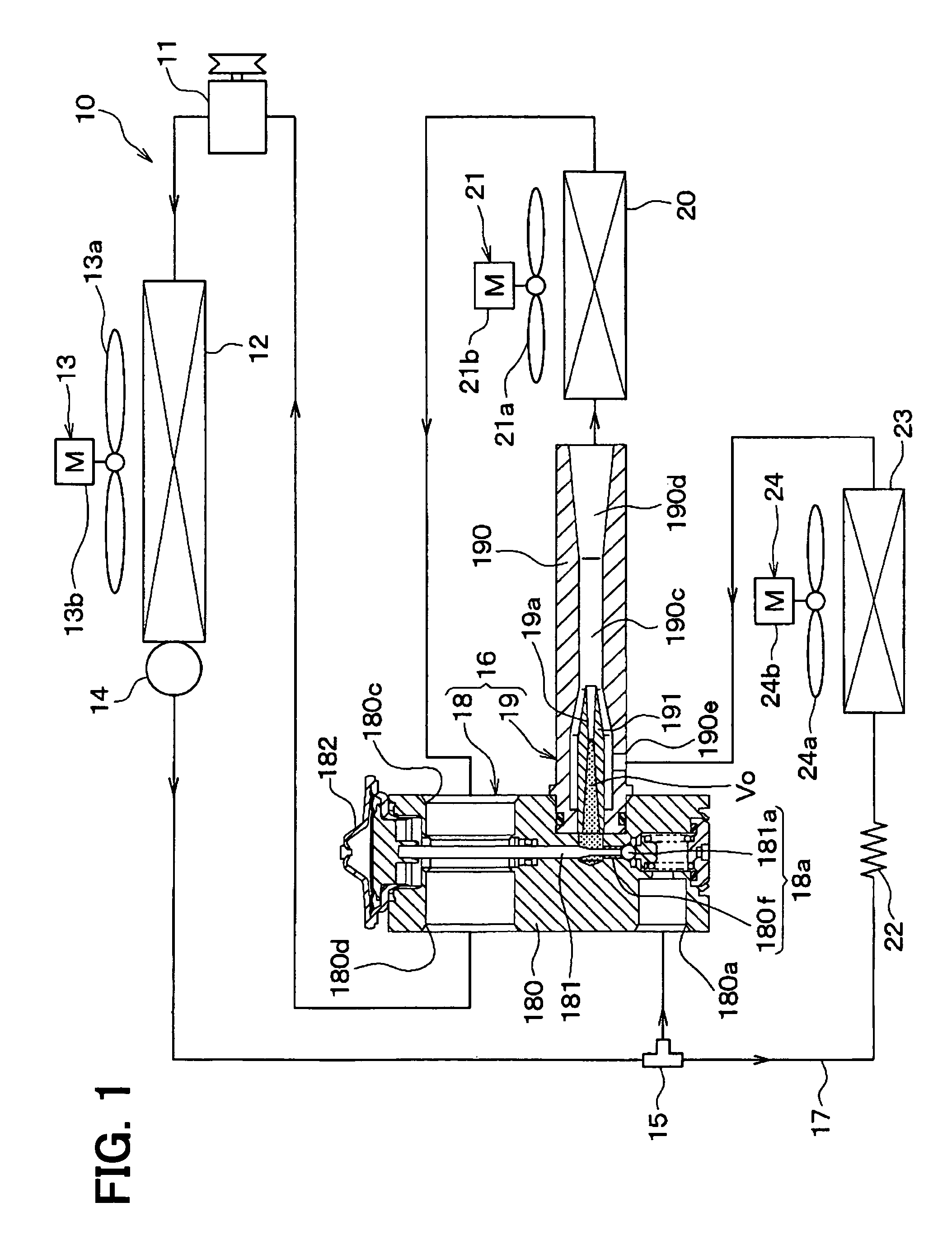
[0029]According to a second aspect of the present invention, an ejector-type refrigeration cycle device includes the two-stage decompression ejector according to the first aspect of the present invention. Accordingly, the low-frequency abnormal noise generated at the two-stage decompression ejector on startup of the ejector-type refrigeration cycle device can be prevented.

Problems solved by technology

It is found that the increase in noise level NL is caused by high-frequency noise, such as frictional noise, generated when the refrigerant passes through the cycle.

Method used


Image

  • Two-stage decompression ejector and refrigeration cycle device
  • Two-stage decompression ejector and refrigeration cycle device
  • Two-stage decompression ejector and refrigeration cycle device

Examples


first embodiment

[0042]A first embodiment of the present invention will be described below with reference to FIGS. 1 and 2. In the present embodiment, an ejector-type refrigeration cycle device 10 including a two-stage ejector 16 of the invention is applied to an air conditioner for a vehicle. FIG. 1 shows the entire configuration of the ejector-type refrigeration cycle device 10. In the ejector-type refrigeration cycle device 10, a compressor 11 for sucking and compressing refrigerant is rotatably driven by a vehicle engine (not shown) by an electromagnetic clutch, a belt, or the like.

[0043]As the compressor 11, may be used either of a variable displacement compressor for being capable of adjusting a refrigerant discharge capacity depending on a change in discharge capacity, or a fixed displacement compressor for adjusting a refrigerant discharge capacity by changing an operating efficiency of the compressor by intermittent connection of the electromagnetic clutch. The use of an electric compressor...

second embodiment

[0095]In the first embodiment, the thermal expansion valve 18 and the ejector 19 are integrally connected together to form the two-stage decompression ejector 16. Alternatively, in the present embodiment, a thermal expansion valve and an ejector are integrally formed as shown in FIGS. 3 and 4 thereby to construct a two-stage decompression ejector 26. FIGS. 3 and 4 illustrate the same or equivalent components as those of the first embodiment by the same reference numerals. The same goes for the following drawings.

[0096]FIG. 3 is a diagram showing the entire configuration of the ejector-type refrigeration cycle device 10 of the present embodiment. FIG. 4 is a sectional view of the two-stage decompression ejector 26. The two-stage decompression ejector 26 of the present embodiment includes a housing 260 corresponding to the thermal expansion valve 18 of the first embodiment, a needle valve 261, a temperature sensing portion 262, a body 190 corresponding to the ejector 19 of the first e...

third embodiment

[0107]In the second embodiment, the two-stage decompression ejector 26 operates the needle valve 261 by use of the temperature sensing portion 262 serving as a superheat-degree actuated mechanism to adjust a throttle passage area of the variable throttle mechanism 26a such that the superheat degree of the refrigerant on the outlet side of the first evaporator 20 becomes a predetermined value. In the present embodiment, as shown in the entire configuration diagram of FIG. 5, a two-stage decompression ejector 27, which can electrically control the operation of the needle valve 261, is used.

[0108]In the two-stage decompression ejector 27 of the present embodiment, the needle valve 261 is driven by an electric actuator 270. As the electric actuator 270, for example, a motor actuator, such as a stepping motor, or an electromagnetic solenoid mechanism can be employed.

[0109]The electric actuator 270 is driven and controlled by a control signal output from a controller 30. The controller 30...


PUM


Abstract

A two-stage decompression ejector includes a variable throttle mechanism having a first throttle passage for decompressing a fluid and a valve body for changing a throttle passage area of the first throttle passage, a nozzle having therein a second throttle passage for further decompressing the fluid decompressed by the variable throttle mechanism, and a suction portion for drawing a fluid by a suction effect of a high-velocity jet fluid from the nozzle. The formula of 0.07≦Vo×S / vn≦0.7 is satisfied, in which Vo is an intermediate-pressure space volume (mm3) from an outlet of the variable throttle mechanism to an inlet of the second throttle passage, S is a throttle passage sectional area (mm2) of a minimum passage sectional area portion of the second throttle passage, and vn is a flow velocity (mm / s) of the fluid passing through the minimum passage sectional area portion.

Description

CROSS REFERENCE TO RELATED APPLICATION[0001]This application is based on Japanese Patent Application No. 2007-153806 filed on Jun. 11, 2007, the contents of which are incorporated herein by reference in its entirety.FIELD OF THE INVENTION[0002]The present invention relates to a two-stage decompression ejector for decompressing and expanding a fluid by using two throttles, and a refrigeration cycle device including the two-stage decompression ejector.BACKGROUND OF THE INVENTION[0003]A refrigeration cycle device is conventionally proposed which uses an ejector as decompression means for decompressing and expanding refrigerant.[0004]This kind of ejector-type refrigeration cycle device is designed to draw refrigerant flowing from an evaporator by a suction effect of a refrigerant flow jetted at a high velocity from a nozzle of an ejector, and to increase a refrigerant pressure to be drawn into a compressor by a diffuser of the ejector. Thus, the refrigerant pressure to be drawn into the...

Claims


Application Information

Patent Timeline
Patent Type & Authority Patents(United States)
IPC IPC(8): F25B1/06F04F5/22
CPCF25B41/00F25B2341/0012F25B2500/01F25B2500/12F25B2341/0013F25B2341/0683F25B2700/21151B60H2001/3298
Inventor OSHITANI, HIROSHITAKANO, YOSHIAKIGOCHO, MIKA
Owner DENSO CORP
Why Eureka
Try Eureka