Axial Hall accelerator with solenoid field

a solenoid field and accelerator technology, applied in the direction of plasma technique, mechanical equipment, machines/engines, etc., can solve the problem of limited prior art ion injection methods

Active Publication Date: 2010-11-02
MOREHOUSE MARK EDWARD
View PDF20 Cites 3 Cited by
  • Summary
  • Abstract
  • Description
  • Claims
  • Application Information

AI Technical Summary

Benefits of technology

[0014]In general, the invention is directed toward an ion accelerator comprising a collimating gas source and an anode external of a solenoid for producing a magnetic field and an electron source cathode beyond the proximal (entrance) fringe, contained in a vacuum space. An embodiment has a proximal entrance end with an annular vacuum gap adapted for a fringe radial magnetic field in the vicinity of the annular vacuum gap. The annular collimating gas source is adapted for directing gas past an anode electron extraction apparatus associated with a source of electric power. The collimated gas is directed into the annular vacuum gap wherein a fringe radial magnetic field forms a Hall effect field in conjunction with an anode and a cathode electron source. An annular ion beam is formed from the neutral gas by electron impact ionization. The ion beam is accelerated into the solenoid by the electric field established between the anode and the cathode.

Problems solved by technology

The prior art ion injection methods are limited by issues of ion trapping as well as space charge neutralization.

Method used


Image

  • Axial Hall accelerator with solenoid field
  • Axial Hall accelerator with solenoid field
  • Axial Hall accelerator with solenoid field

Examples


first embodiment

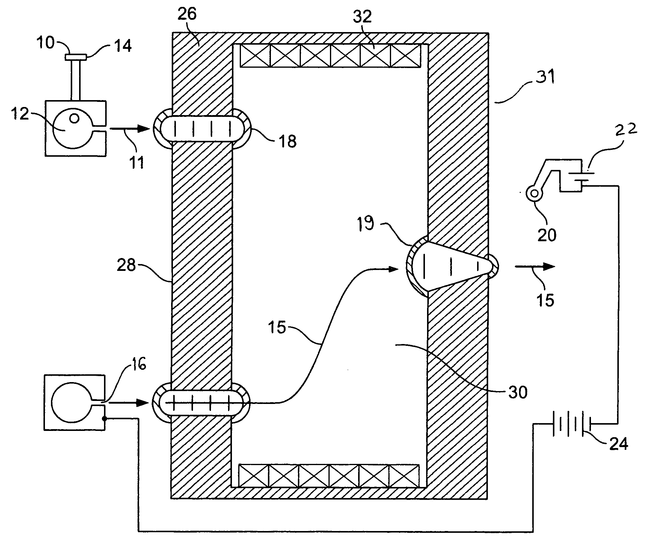
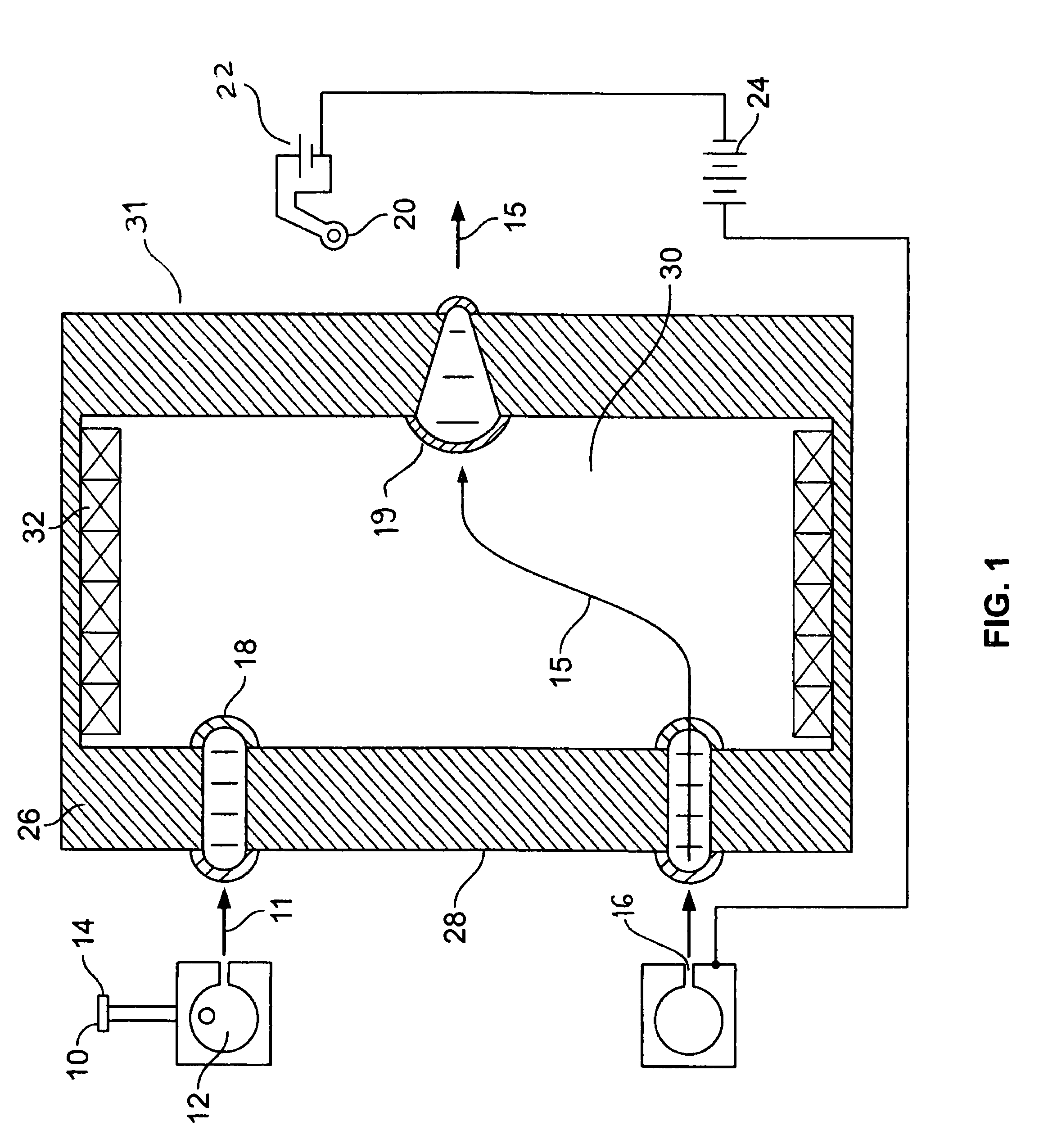
[0031]FIG. 1 reveals the present invention. Gas 10 is introduced into a plenum 12 through a gas input port 14. The gas 10 expands supersonically through an annular Laval type nozzle 16 forming an annular gas sheath 11 traveling through a vacuum on axis with a solenoid 31. Gas sheath 11 is ionized by electrons that transit through the Hall fields 19 and 18 from electron source 20 and 22 under the influence of acceleration power supply 24. The ions 15 are accelerated through the two Hall effect radial fringe fields 18 and 19 by the acceleration power supply 24. The first of two Hall fringe fields, entrance fringe field 18, is established between a return flux iron core 26 and a fringe core 28. Within the entrance fringe field 18 the ions' 15 original axial trajectory is bent as the ions are accelerated into energetic azimuthal orbits which then spiral though the solenoid field 30 maintained by solenoid windings 32. The axial extent of the solenoid is such that the ions are on axis whe...

second embodiment

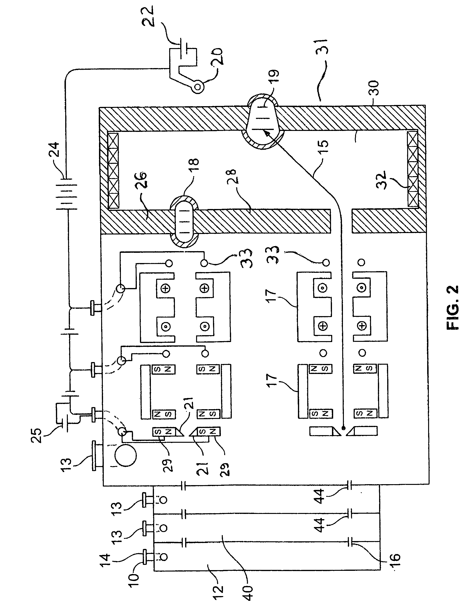
[0032]FIG. 2 reveals the present invention. Gas 10 is introduced into Gas plenum 12 through gas input port 14 which expands supersonically through a directional annular convergent-divergent type nozzle 16 into a differential pumping chamber(s) 40, with vacuum pumping port(s) 13, where neutral gas atoms that are not traveling on axis are stripped away by a second, or more, collimating gas throats 44, resulting in a higher degree of axial collimation of the streaming gas. The anode structure is comprised of a pair of electrodes 21 and a bias power supply 25, which provides a voltage potential between the two electrodes 21. Electrodes 21 are on common Hall effect magnetic field lines established by Hall effect magnetic field structures 29 or 26 and 28. Intermediate magnetic field structures allow the electrode bias supply 25 to divert electrons to the more positive of the two electrodes 21 which then forms the anode of the acceleration power supply 24. The gas source 16 or 44 may alter...


PUM


Abstract

The present patent letters discloses a Hall Current accelerator with a solenoid Hall field, a collimated gas source, an anode, intermediate Hall effect ionization magnetic field structures and intermediate acceleration electrodes. The Hall field in this case is the end fringe field(s) of a common solenoid magnetic field.

Description

BACKGROUND OF THE INVENTION[0001]1. Field of the Invention[0002]The present invention is directed generally to a closed drift Hall type accelerator in a vacuum space.[0003]2. Description of Related Art[0004]The present invention attempts to achieve a high energy ion beam source which is superior to existing accelerators in beam density and energy. Hall Current accelerators operate without space charge limitations as are present in conventional ion beam accelerators, which use electrostatic lens (grids) to extract ions from a neutral plasma (gridded ion sources). Such devices can have very good optics. That is they can have a very well defined velocity vector and energy spread.[0005]In Hall accelerators ion acceleration is achieved by providing a voltage potential between an anode associated with a neutral gas source and a cathode in the general vicinity of the beam exit. Electrons from the cathode migrate through the Hall effect fields, which pick up the electrons in E×B azimuthal o...

Claims


Application Information

Patent Timeline
Patent Type & Authority Patents(United States)
IPC IPC(8): H05B31/26
CPCF03H1/0075H05H1/54
Inventor MOREHOUSE, MARK EDWARD
Owner MOREHOUSE MARK EDWARD
Why Eureka
Try Eureka