
Process for finish-machining crank shafts for motor car engines

Inactive Publication Date: 2010-11-09
HEGENSCHEIDT MFD
View PDF10 Cites 15 Cited by
  • Summary
  • Abstract
  • Description
  • Claims
  • Application Information

AI Technical Summary

Benefits of technology

[0007]The object of the present invention is to obtain bearing positions of the greatest possible width on a crankshaft and, in this situation, at the same time to increase their fatigue strength by a perceptible degree.
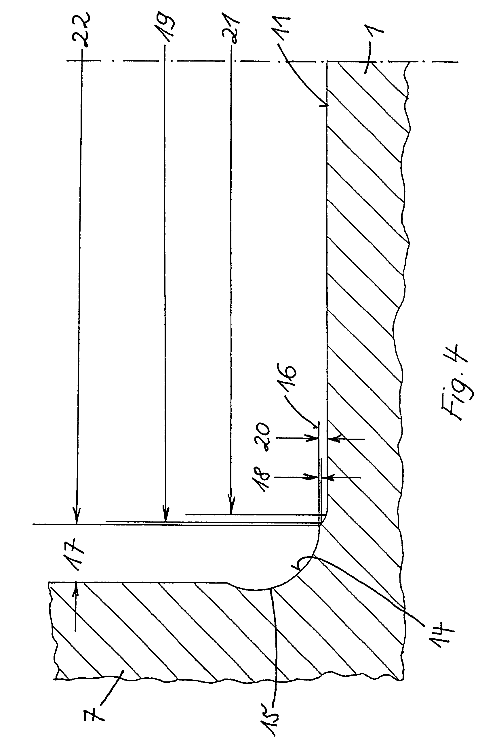
[0011]In this way, only a little of the favourable pressure internal stress course caused by the deep rolling will be removed in the fillet, so that the pressure internal stress state of the crankshaft is largely retained. Also, in this way, bearing positions can be created which are broader than usual. This is possible in that the grinding disk or the tool with which the bearing position is fine-machined does not come in contact with the radius in the transition between the bearing position and the adjacent cheek, but material is only removed at the edge of the rolling in area thrown up by the deep rolling. As a consequence of this, the removal of material during the finish-machining of the bearing positions can be kept low, and amounts to only between 0.1 to 0.3 mm. The method is therefore particularly well-suited for the fine-machining of crankshafts hardened on the running surfaces of the bearings, whereby the penetration depth of the hardening can be small because of the small amount of material removed.
[0012]The rolling-in depth of the roundings is derived from the increase in fatigue strength which is required. In most cases it amounts to 0.2 mm. In comparison with deep rolled recesses, the rolling-in depth of the roundings can be lower.

Problems solved by technology

As a result of the pressing of the hard deep rolling rollers, plastic deformation occurs between the transition, such as for example the cheek or the adapting bearing of the crankshaft, and the bearing position, and in this way induces a state of pressure internal stresses into the crankshaft, which increases the fatigue strength of the crankshaft.
In particular, recesses or fillets increase the level of tension on crankshafts under flexural and torsion stress, because at the same time they weaken the diameter at the transition to the cheek.
Accordingly, the edges which are required for technical application reasons on dynamically highly-stressed parts are rounded or prepared with fillets, which then lead to an increase in the fatigue strength of the crankshaft.

Method used


Image

  • Process for finish-machining crank shafts for motor car engines
  • Process for finish-machining crank shafts for motor car engines
  • Process for finish-machining crank shafts for motor car engines

Examples


Embodiment Construction

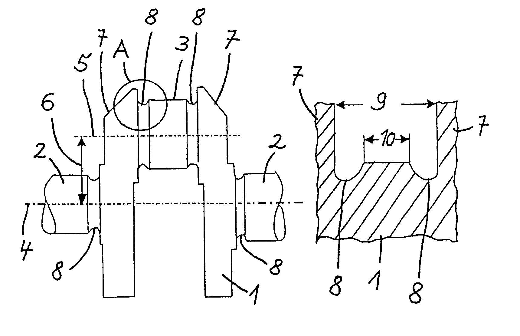
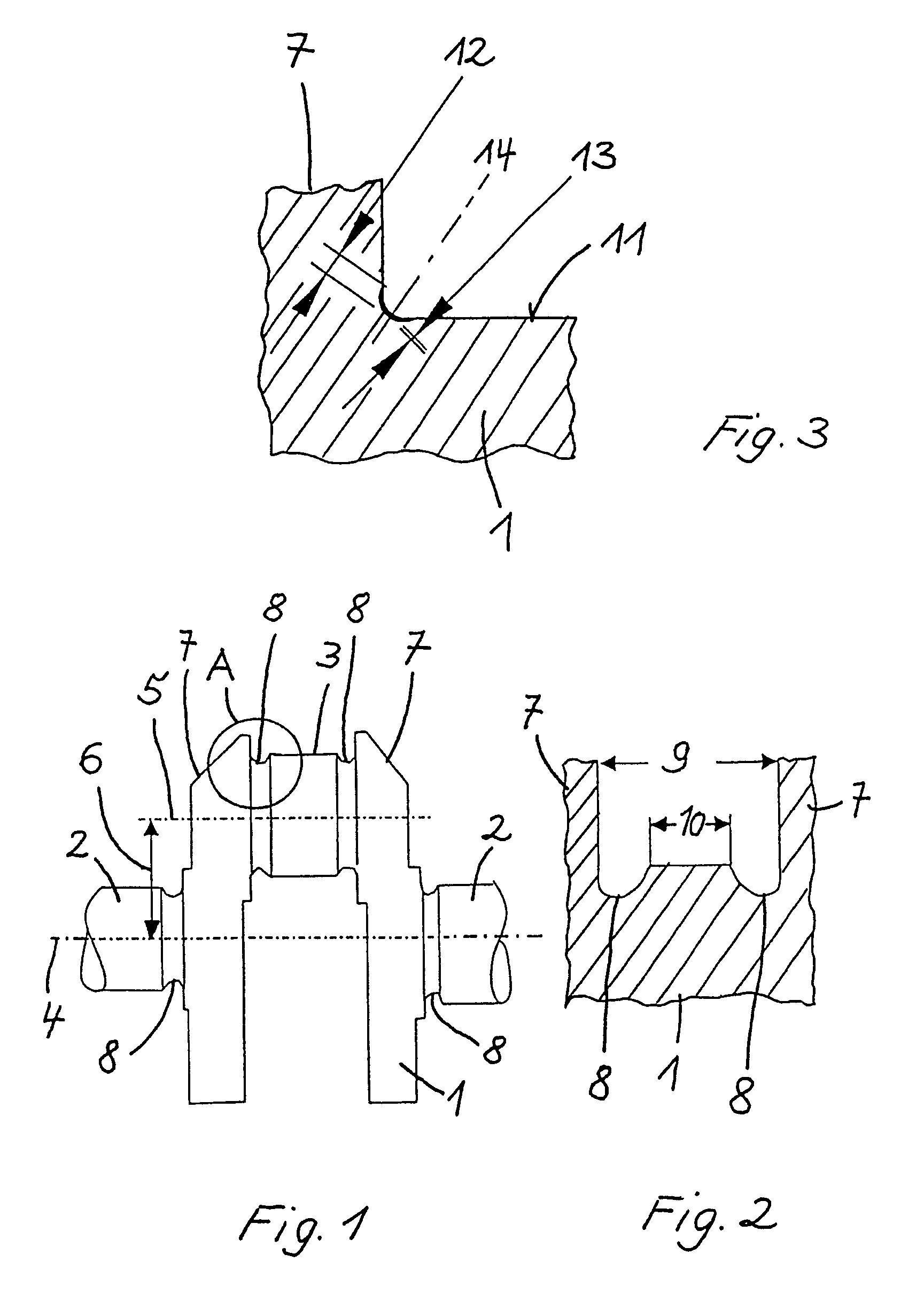
[0022]The crankshaft 1 has two main bearing journals 2 and a stroke bearing journal 3. The crankshaft 1 is mounted in the engine block (not shown) of a motor car engine so as to rotate about the axis of rotation 4 with the two main bearing journals 2. The axis of rotation 5 of the stroke bearing journal 3 is at a distance 6 from the axis of rotation 4 of the crankshaft 1, this distance corresponding to the stroke. The transitions between the two main bearing journals 2 and the stroke bearing journal 3 are formed by the two cheeks 7. Between the main bearing journals 2, the stroke bearing journal 3, and the individual transitions 7, provision is made in each case for fillets 8. The largest theoretically available bearing width 9 is reduced by the two fillets 8 to the actually available bearing width 10, as can be seen in FIG. 2.

[0023]In accordance with the invention, the bearing position 11, which pertains to a main bearing journal 2 or a stroke bearing journal 3, is deep rolled with...


PUM

PropertyMeasurementUnit
Radiusaaaaaaaaaa
Radiusaaaaaaaaaa
Depthaaaaaaaaaa

Abstract

The invention relates to a process for finish-machining of bearing positions on main bearing journals and connecting rod bearing journals of crankshafts for motor car engines, whereby the crankshafts have roundings between the bearing positions and transitions adjacent in each case to the bearing positions. The roundings are deep rolled with a deep rolling tool and then, while maintaining a distance interval to an individual transition in each case the bearing position concerned is machined with removal of material with a small cutting depth.

Description

[0001]This application is a National Phase Application of International Application No. PCT / EP2003 / 08575, filed on Aug. 2, 2003, which claims the benefit of and priority to German patent application no. DE 102 35 957.1-14, filed Aug. 6, 2002. The disclosure of the above applications are incorporated herein by reference in their entirety.BACKGROUND OF THE INVENTION[0002]The invention relates to a process for the finish-machining of the bearing positions on main bearing journals and connecting rod bearing journals of crankshafts for motor car engines, whereby the crankshafts have roundings between the bearing positions and the transitions adjacent in each case to the bearing positions, such as for example cheeks or adapting bearings.[0003]To increase the fatigue strength of the crankshaft of engines for motor vehicles, the transitions at the bearing positions of the main bearing journals and connecting rod bearing journals are deep rolled. In this situation, deep rolling rollers, whic...

Claims


Application Information

Patent Timeline
IPC IPC(8): B23P17/00B21H7/18B23P9/02B24B5/42F16C3/08
CPCB21H7/185B23P9/02F16C3/08B24B5/42Y10T29/49231Y10T29/49286
Inventor HEIMANN, ALFREDKLOMP, REINHARDREIM, PETER
Owner HEGENSCHEIDT MFD
Learn More