Ultra low emissions fast starting power plant

a power plant and low emission technology, applied in the direction of machines/engines, indirect carbon-dioxide mitigation, mechanical equipment, etc., can solve the problems of high cost, low efficiency, and many low-efficiency combustion-based electric power sources, and achieve the effect of low emissions and fast starting

Inactive Publication Date: 2010-11-09
CLEAN ENERGY SYST
View PDF6 Cites 113 Cited by
  • Summary
  • Abstract
  • Description
  • Claims
  • Application Information

AI Technical Summary

Benefits of technology

[0031]Another object of the present invention is to provide a power generation system which utilizes on-site storage of reactants and other necessary supplies to operate on the order of hours without requiring continuous reactant delivery.
[0032]Another object of the present invention is to provide a power generation system which can be built at a minimum of capital expenses and provide power on the order of megawatts in a fast starting low emissions fashion.
[0033]Another object of the present invention is to provide a power generation system which can operate without concern for availability of wind, sunlight or water storage in a reservoir, to meet peak electric demand, with little or not atmospheric emissions.

Problems solved by technology

Some sources of electric power are necessarily intermittent, making their availability for peak power demand unreliable.
For instance, solar power is only available during clear daylight hours.
Unfortunately, many lower efficiency (higher cost) combustion based electric power sources that are suitable for reliable use upon peak power demand are also relatively large emitters of atmospheric pollution.
Hence, even though power plants may exist and be available to meet peak demand on the electric grid, the high emissions of such lower efficiency combustion based power plants make their utilization undesirable (or legally precluded).
While such systems benefit additionally from the highest electric power generation efficiency possible, the need for high efficiency is less critical in such peak demand situations, such that this need can be met with lower efficiency technology, especially when accompanied by lower capital costs to implement such systems.
CAES systems are limited by the need to be near an appropriate geological formation and have no low pollution benefit and so need to comply with more difficult emissions requirements.
However, often peak electric power demand occurs when air temperatures are highest, due to air conditioner loads.
Thus, when needed the most, these heat engine power plants often suffer from somewhat reduced power output.
However, for a refrigeration system to cool the air to this degree would require a large portion of the power saved and increase capital expenses to build such a plant.

Method used


Image

  • Ultra low emissions fast starting power plant
  • Ultra low emissions fast starting power plant
  • Ultra low emissions fast starting power plant

Examples


Embodiment Construction

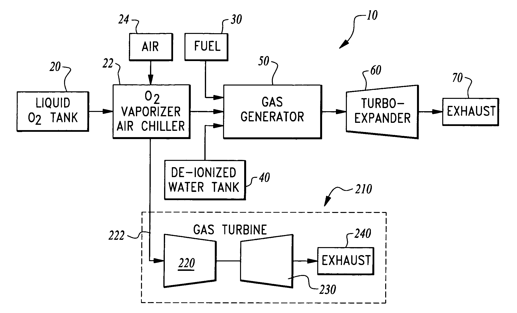
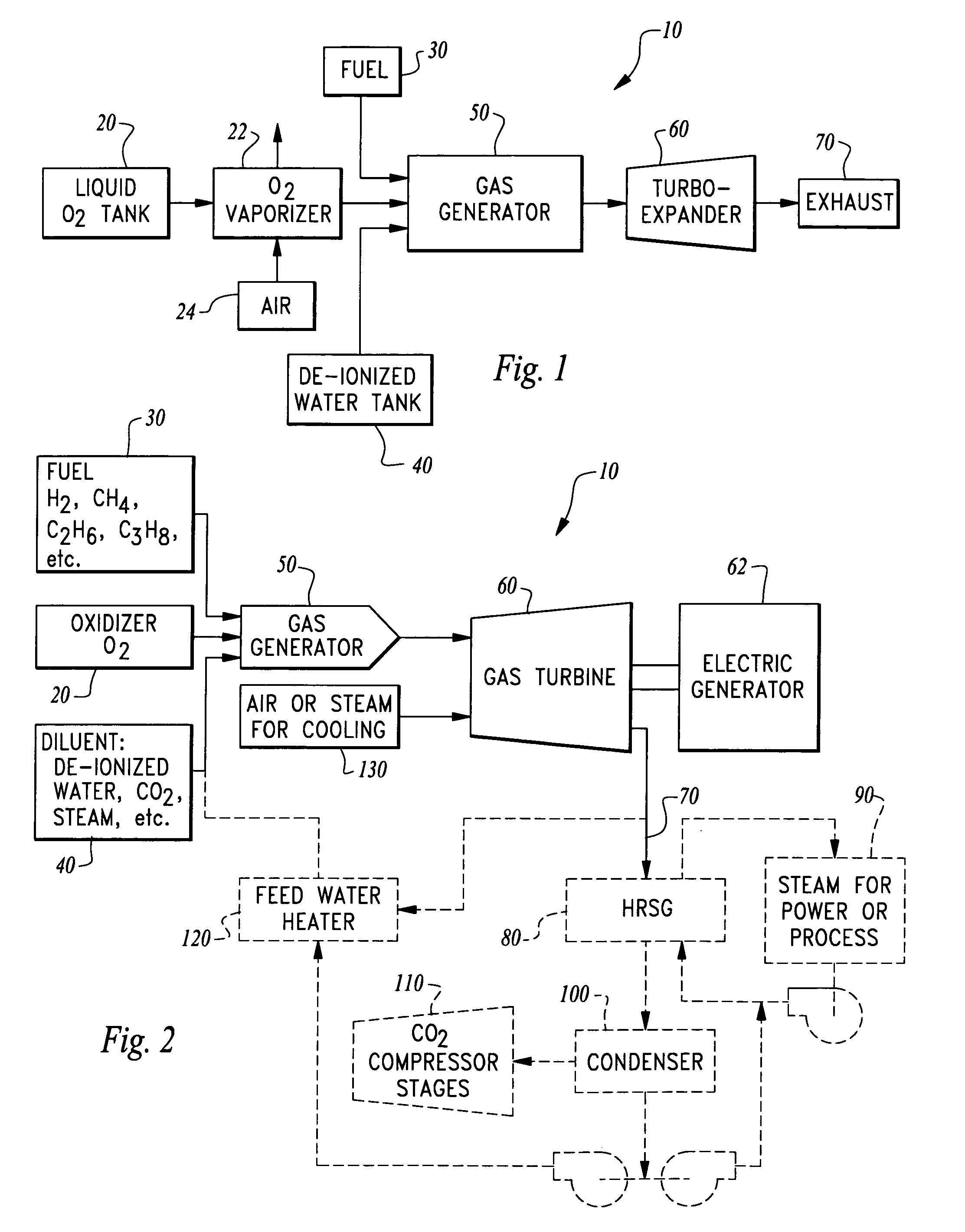
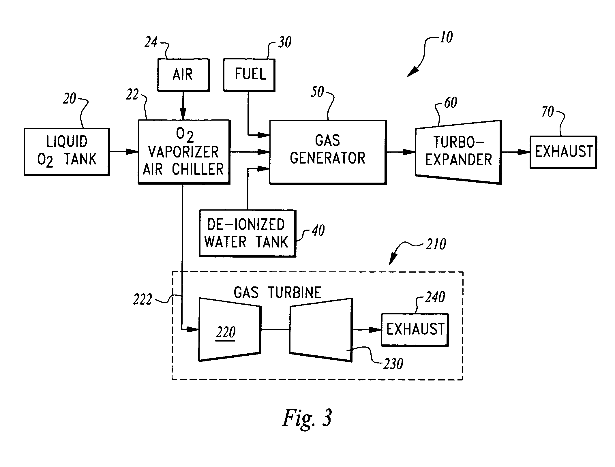
[0038]Referring to the drawings, wherein like reference numerals represent like parts throughout the various drawing figures, reference numeral 10 is directed to an ultra low emissions power generation system (FIG. 1). This system 10 is capable of relatively high power output (10-200 MW or more) in a configuration which facilitates fast starting suitable for peak power supply. The system 10 does not necessarily require separate continuous sources of fuel and oxygen, but rather preferably has consumables stored in tanks or other reservoirs ready for use and operation for periods on the order of hours, such as to meet peak demand of the electricity grid. Because the fuel is combusted with oxygen rather than air, oxides of nitrogen are minimally produced, such that the power generation system 10 can be sited in locations where emissions restrictions would otherwise deter or preclude additional power generation.

[0039]In essence, and with particular reference to FIG. 1, basic details of ...


PUM


Abstract

The power plant combusts a hydrocarbon fuel with oxygen to produce high temperature high pressure products of combustion. These products of combustion are routed through an expander to generate power. The products of combustion are substantially free of oxides of nitrogen because the oxidizer is oxygen rather than air. To achieve fast starting, oxygen, fuel and water diluent are preferably stored in quantities sufficient to allow the power plant to operate from these stored consumables. The fuel can be a gaseous or liquid fuel. The oxygen is preferably stored as liquid and routed through a vaporizer before combustion in a gas generator along with the hydrocarbon fuel. In one embodiment, the vaporizer gasifies the oxygen by absorption of heat from air before the air is routed into a separate heat engine, such as a gas turbine. The gas turbine thus operates on cooled air and has its power output increased.

Description

CROSS-REFERENCE TO RELATED APPLICATIONS[0001]This application claims benefit under Title 35, United States Code §119(e) of U.S. Provisional Application No. 60 / 733,638 filed on Nov. 4, 2005 and U.S. Provisional Application No. 60 / 759,139 filed on Jan. 13, 2006.FIELD OF THE INVENTION[0002]The following invention relates to power generation systems which combust a hydrocarbon fuel with oxygen for low emissions power generation. More particularly, this invention relates to configurations of oxyfuel combustion power generation systems which can be quickly started and which are optimized for peak demand electric power generation by producing relatively high power output and potentially also enhancing power output from adjacent existing power generation systems.BACKGROUND OF THE INVENTION[0003]To maintain electric power distribution “grids” in proper working order, it is important that the supply of electric power into the grid be maintained a safe margin above the demand caused by users o...

Claims


Application Information

Patent Timeline
Patent Type & Authority Patents(United States)
IPC IPC(8): F02G3/00F02C3/00
CPCF01K23/10F02C3/22F02C3/24F02C3/30F02C7/143Y02E20/16Y02E20/34
Inventor PRONSKE, KEITH L.VITERI, FERMINMACADAM, SCOTTHOFFMAN, LAWRENCE C.
Owner CLEAN ENERGY SYST
Why Eureka
Try Eureka