System and method for integrated air separation and liquefaction

a technology of applied in the field of integrated air separation and liquefaction, can solve the problems of high capital cost and power consumption of air separation units, difficult compression power and capital cost problems associated with distillation column based air liquefaction processes, and high cost, and achieve significant capital cost savings, increase the overall compression ratio, and reduce the effect of air compressor system discharge pressur

Inactive Publication Date: 2016-08-25
PRAXAIR TECH INC
View PDF4 Cites 3 Cited by
  • Summary
  • Abstract
  • Description
  • Claims
  • Application Information

AI Technical Summary

Benefits of technology

[0017]Advantageously, the recycle compression necessary to power warm level refrigeration is generated without an externally powered compressor. The elimination of a separate drive means, power supply and lubrication system offers a significant capital cost savings. In addition, the main driver for product liquefaction is primarily shifted toward the main air compressor. In particular, the discharge pressure of the main feed air compressor system is substantially increased over many conventional main feed air compressor systems. By increasing the overall compression ratio on the main feed air compressor system one can achieve enhance liquefaction capability with a minimum in incremental capital expense.
[0018]Another aspect that differentiates the present invention from the prior art systems is the use or introduction of a warm gas turbo-expansion as supplemental refrigeration. In general, it has been found that the introduction of a warm gas turbo-expansion will enable the production of an additional 5% to 10% of the incoming feed air as liquefied product. This incremental liquid production can be typically gained at low incremental power consumption which provides the main economic advantage of the present system and method. By recycling the streams only from the warm turbine, the irreversibility associated with prior art cold recycle systems is eliminated. In particular, the incremental liquefaction from about 10%-15% of the incoming feed air to greater than 15% of the incoming feed air is achieved using warm turbo-expansion at roughly half the unit power typically associated with cold turbo-expansion that is used or contemplated in various prior art systems.
[0020]In addition to lower power consumption, by producing a significant liquid fraction, i.e., over 15% of the feed air produced as liquid, the present system and method enables the near complete liquefaction of the oxygen contained in the incoming feed air. In such situations, the pump and piping associated with prior art pumped liquid oxygen product stream can be eliminated with a further appreciable capital cost savings.

Problems solved by technology

However, the air liquefaction process requires additional refrigeration to be supplied to the air separation unit which drives up the capital costs and power consumption of the air separation unit.
Compression power and capital cost problems associated with the distillation column based air liquefaction processes are particularly challenging in small to medium sized air separation plants.
The use of warm recycle compression-expansion circuits in such small to medium sized plants to improve the air liquefaction process has been tried but is somewhat expensive and introduces unwanted process complexities to the overall air separation process.

Method used


Image

  • System and method for integrated air separation and liquefaction
  • System and method for integrated air separation and liquefaction
  • System and method for integrated air separation and liquefaction

Examples


Embodiment Construction

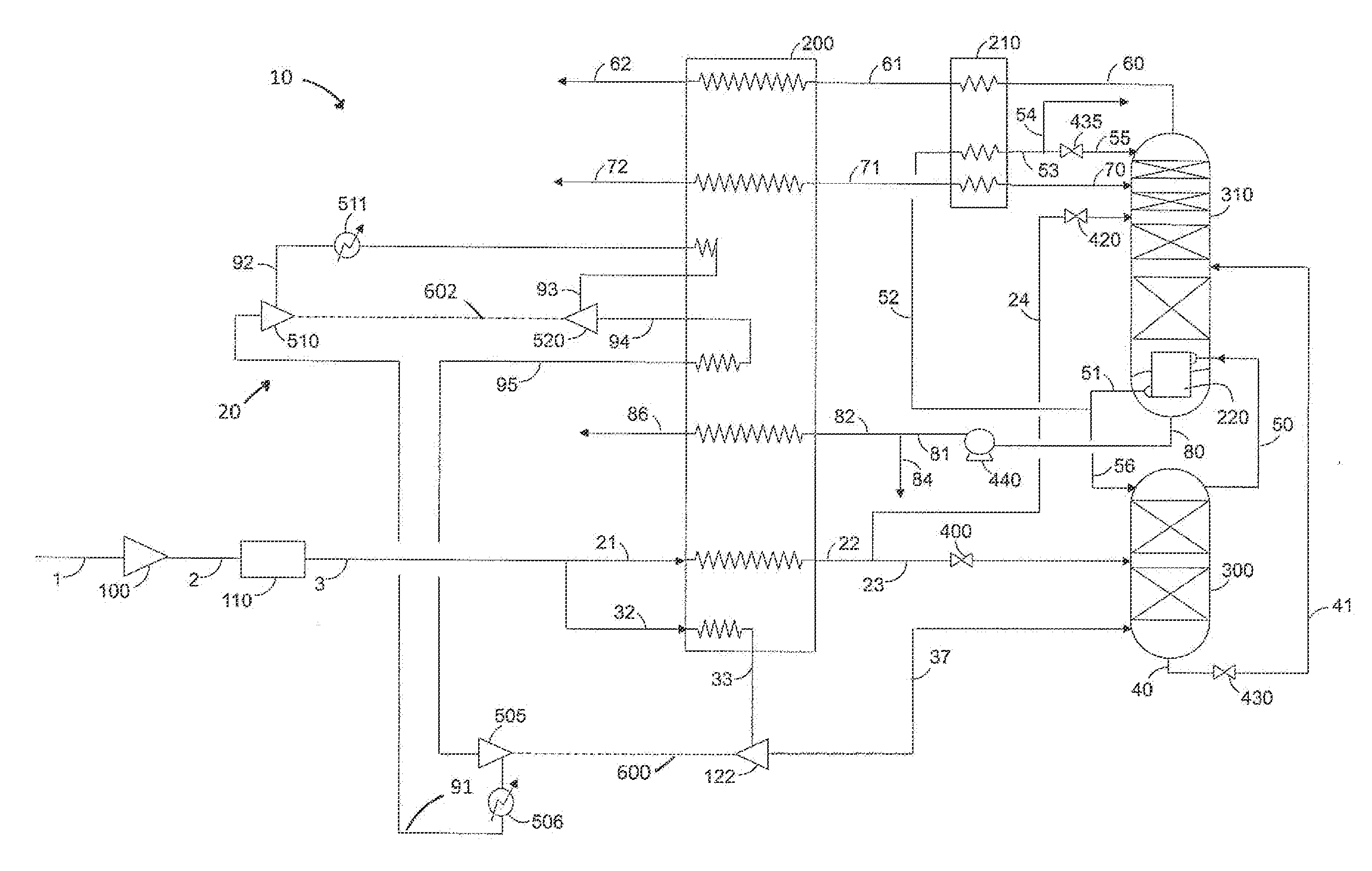
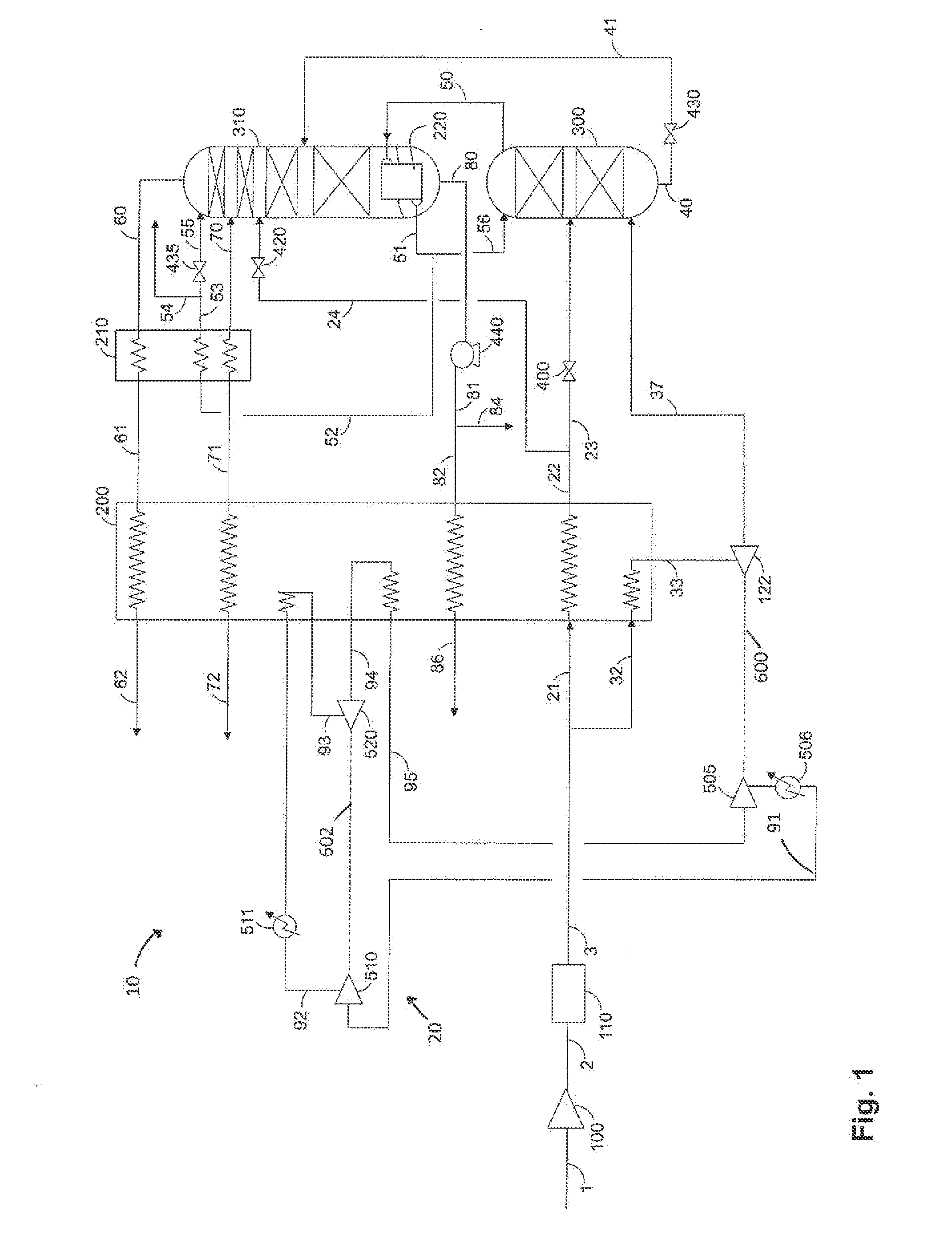
[0024]With reference to FIG. 1, a double column, cryogenic air separation plant 10 is illustrated that is integrated with a closed loop supplemental refrigeration circuit or warm recycle expansion circuit 20, discussed hereinafter, to increase production of liquid products such as liquid oxygen or liquid nitrogen. The operation of this thermally linked, double column distillation system is well known to the art of air separation. It is also understood by those skilled in the art, that if argon were a necessary or desired product, an argon column (or columns) could be incorporated into the distillation system.

[0025]Feed air stream 1 is first compressed in a multi-stage air compression system 100 with intercooling and condensate removal (not shown for simplicity) to a substantially elevated pressure in the range of about 40 to about 60 bar. The compressed air stream 2 is then directed to a pre-purification unit 110. The pre-purification process undertaken by the pre-purification unit ...


PUM


Abstract

A high efficiency and high volume air liquefaction system and method is disclosed wherein the cryogenic air separation plant includes a warm gas turbo-expansion cycle to supply the supplemental refrigeration required to produce liquid products in excess of about 15% of the incoming feed air.

Description

FIELD OF THE INVENTION[0001]The present invention relates to a system and method for producing one or more liquid product streams by cryogenic rectification of air or other feed stream, and more particularly, a system and method for converting upwards of 20% of the incoming air or other feed stream into one or more liquid product streams.BACKGROUND OF THE INVENTION[0002]Oxygen and nitrogen are produced commercially in large quantities by the cryogenic distillation of air in air separation units (ASU) where incoming feed air is compressed; purified of contaminants; and then cooled in a main heat exchanger to a temperature suitable for its rectification. The compressed, purified and cooled air stream is then cryogenically distilled typically in a thermally integrated dual pressure column system in which air is separated into at least oxygen and nitrogen-rich product streams. As well known in the art, additional columns may be employed to produce argon or additionally rare gases.[0003]...

Claims


Application Information

Patent Timeline
Patent Type & Authority Applications(United States)
IPC IPC(8): F25J3/04
CPCF25J3/04412F25J2270/902F25J3/04175F25J3/04278F25J3/04296F25J3/04345F25J3/04381F25J3/04393F25J2245/40F25J2245/42F25J2270/14F25J2270/40F25J2270/42F25J2270/80F25J2270/90F25J3/0409
Inventor HOWARD, HENRY E.
Owner PRAXAIR TECH INC
Why Eureka
Try Eureka