Reinforced synthetic cable for elevators

a synthetic cable and elevator technology, applied in the field of cables or belts, can solve the problems of reducing the comfort of travel, limiting the travel height of the elevator installation, and accompanied use of steel cables, and achieve the effects of reducing the service life of the cable, and increasing the comfort of travel

Inactive Publication Date: 2010-11-09
INVENTIO AG
View PDF26 Cites 18 Cited by
  • Summary
  • Abstract
  • Description
  • Claims
  • Application Information

AI Technical Summary

Benefits of technology

[0012]An object of the present invention is to propose a cable or belt as a support means or a drive means for elevators of the kind described above, which does not have the aforesaid disadvantages and by means of which travel comfort and safety are increased. In particular, the following disadvantages shall be eliminated: the undesired shortened service life of the cable, the too-small modulus of elasticity of the cable, the undesired elongations of the cable and the troublesome oscillations of the elevator set in motion.
[0018]The reinforced cable obtained in accordance with the present invention demonstrates a higher modulus of elasticity in the longitudinal direction than that of the unreinforced cable. Moreover, the reinforced cable according to the present invention also demonstrates a higher modulus of elasticity, a higher strength and higher breakage strain in a radial direction and a longer service life than those of the cable without reinforcement.

Problems solved by technology

However, the use of steel cables is accompanied by certain disadvantages.
Due to the high intrinsic weight of the steel cable, limits are placed on the travel height of an elevator installation.
In addition, the steel cable acts as a sound bridge between the drive and the car which means a reduction in travel comfort.
Moreover, steel cables tolerate, by comparison with synthetic material cables, a lesser bending cycle rate, are subject to corrosion and have to be regularly serviced.
Notwithstanding the substantial advantages relative to steel cables, the synthetic material cables described in the U.S. Pat. No. 5,566,786 also demonstrate significant limitations, as also stated in the U.S. published application 2002 / 0000347.
Synthetic material cables demonstrate a very good longitudinal strength, which is, however, opposed by poor radial strength.
The synthetic material cables tolerate, with difficulty, the load which is exerted on the outer surface thereof and which can lead to an undesired shortened service life of the cable.
Finally, the modulus of elasticity of the synthetic material cables currently in use is too small for elevators with greater travel heights: undesired elongations of the cable occur and troublesome oscillations of the elevator which is set in motion are noticed by the user, particularly when the length of the cable has exceeded a specific limit.

Method used


Image

  • Reinforced synthetic cable for elevators
  • Reinforced synthetic cable for elevators
  • Reinforced synthetic cable for elevators

Examples


Embodiment Construction

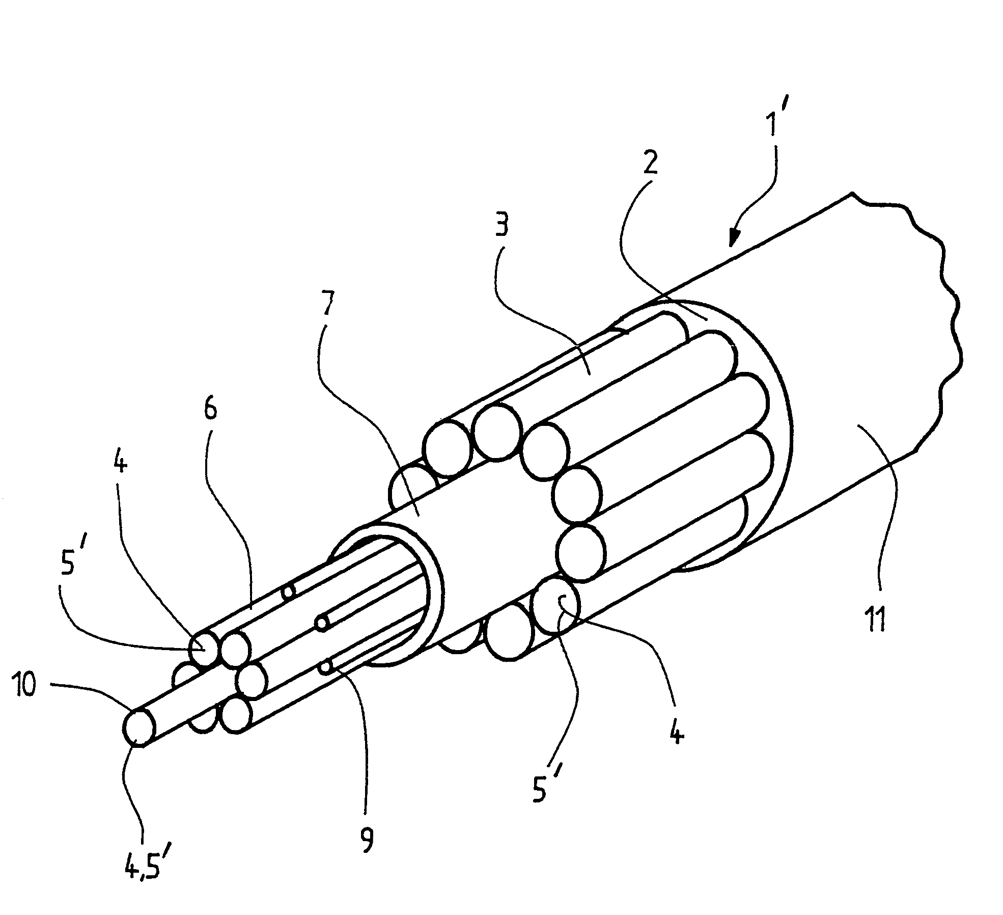
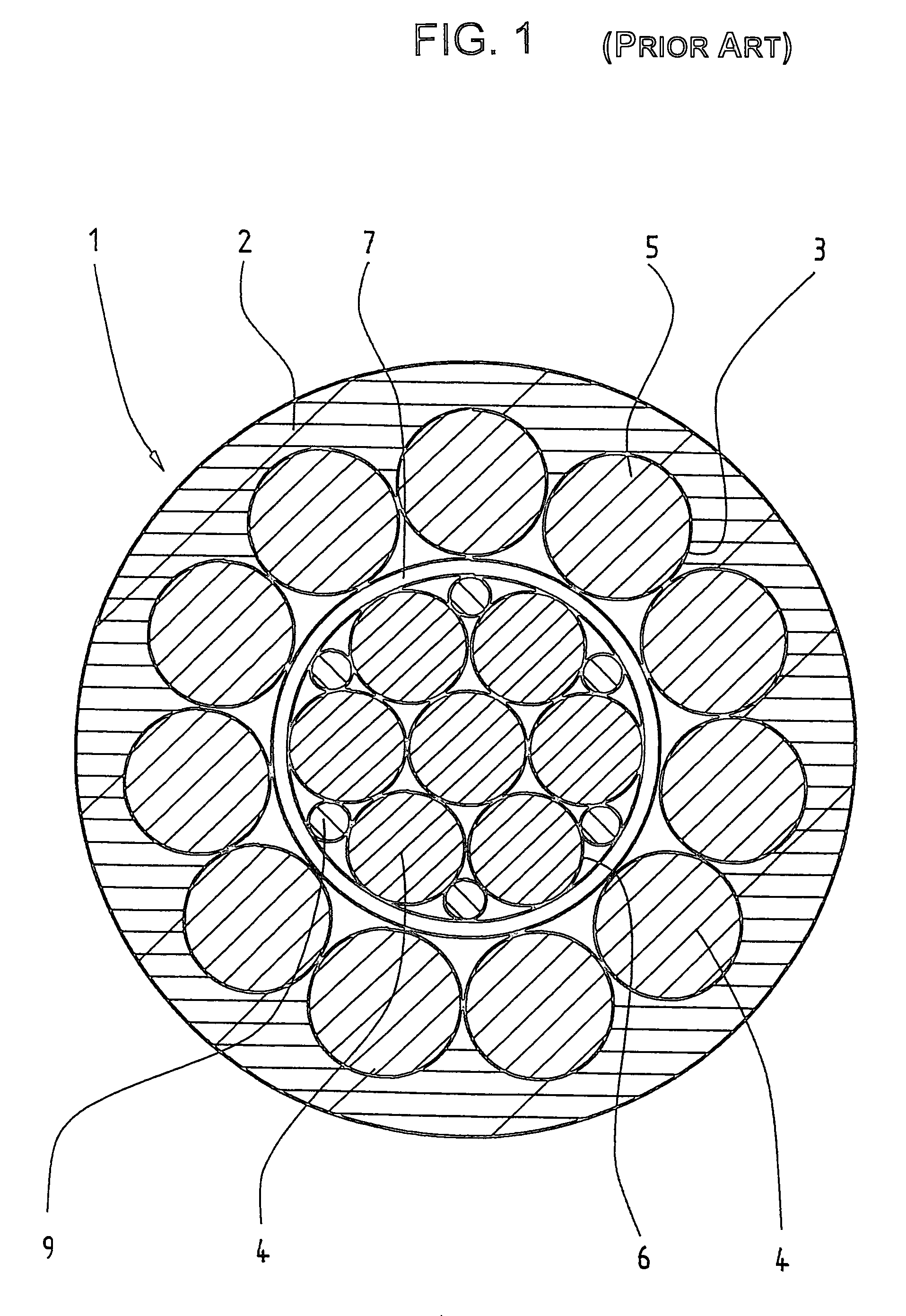
[0029]FIG. 1 shows a section through a conventional synthetic material cable 1. A sheath 2 surrounds an outermost strand layer 3. The sheath 2 is formed of synthetic material, for example polyurethane, that increases the coefficient of friction of the cable 1 on a drive pulley. The outermost strand layer 3 must have such high adhesion forces relative to the sheath 2 that this does not displace due to the thrust forces arising when the cable 1 is loaded or do not form wrinkles. These adhesion forces are achieved in that the synthetic material sheath 2 is injection-molded (extruded) in place so that all interstices in the outer strand carrier are filled and a large retention area is formed (see EP 0 672 781). The strands 4 are twisted or laid from individual fibers 5 of aramid material. Each individual strand 4 is treated with an impregnant, for example polyurethane solution, for protection of the fibers 5. The reverse bending strength of the cable 1 is dependent on the proportion of ...


PUM

PropertyMeasurementUnit
diameteraaaaaaaaaa
modulus of elasticityaaaaaaaaaa
rotational movementaaaaaaaaaa

Abstract

An elevator support, such as a cable or a belt connected with an elevator car or counterweight, has load-bearing synthetic material strands, which are reinforced by the introduction of a second phase and have a higher modulus of elasticity than that of the unreinforced strands.

Description

BACKGROUND OF THE INVENTION[0001]The present invention relates to a cable or belt used as a support means for elevators.[0002]A drive pulley is often used in an elevator installation in order to move a car. In the case of such a drive pulley elevator, the drive pulley and the car are connected together by way of, for example, a cable. A drive unit sets the drive pulley into rotational movement. The rotational movement of the drive pulley is converted into linear movement of the car by a friction couple between the drive pulley and the cable. The cable then serves as a combined support and drive means, whilst the drive pulley serves as a force transmission means:[0003]in its function as a support means the cable supports an operating weight of the elevator, consisting of the empty weight of the car, the useful load of the elevator, an optional counterweight and the weight of the cable. The cable is in that case principally loaded by tension forces. For example, the car and the counte...

Claims


Application Information

Patent Timeline
Patent Type & Authority Patents(United States)
IPC IPC(8): B66B11/04D02G3/00D02G3/02D07B1/16B66B7/06D07B5/00
CPCD07B1/02D07B1/025D07B2201/1008D07B2201/2036D07B2201/2041D07B2201/2087Y10T428/2927D07B2205/205D07B2501/2007D07B2201/2092Y10T428/2931Y10T428/2929D07B2801/10Y10T442/30D07B2201/2014D07B2201/2046
Inventor PARRINI, LORENZO
Owner INVENTIO AG
Why Eureka
Try Eureka