Roller bearing
a roller bearing and roller technology, applied in the direction of sliding contact bearings, mechanical equipment, machines/engines, etc., can solve the problems of excessive internal stress in the cage, restricted axial displacement of the cage, and possible torque loss
- Summary
- Abstract
- Description
- Claims
- Application Information
AI Technical Summary
Benefits of technology
Problems solved by technology
Method used
Image
Examples
embodiment 1
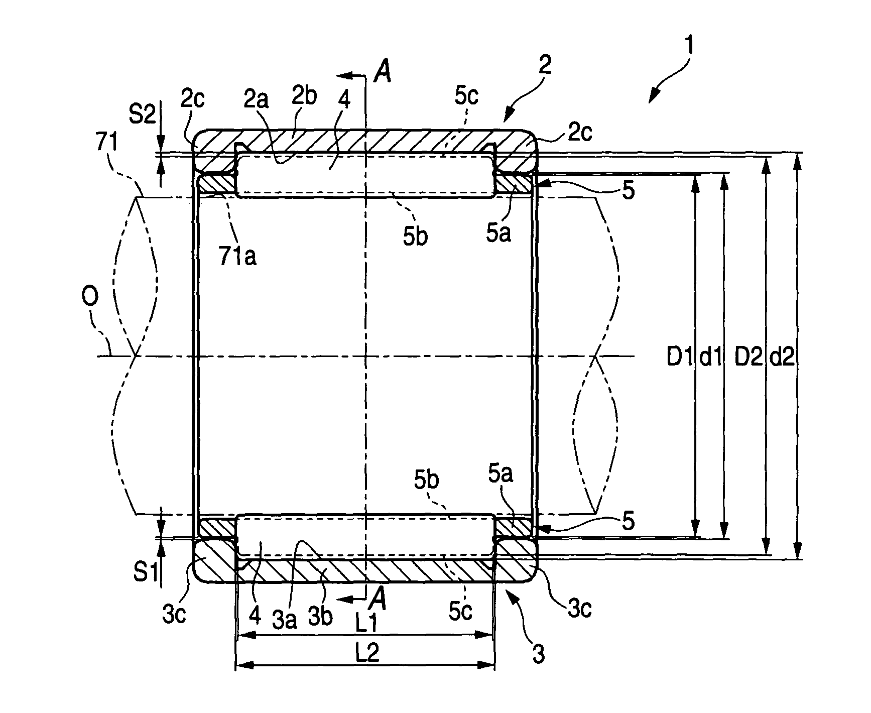
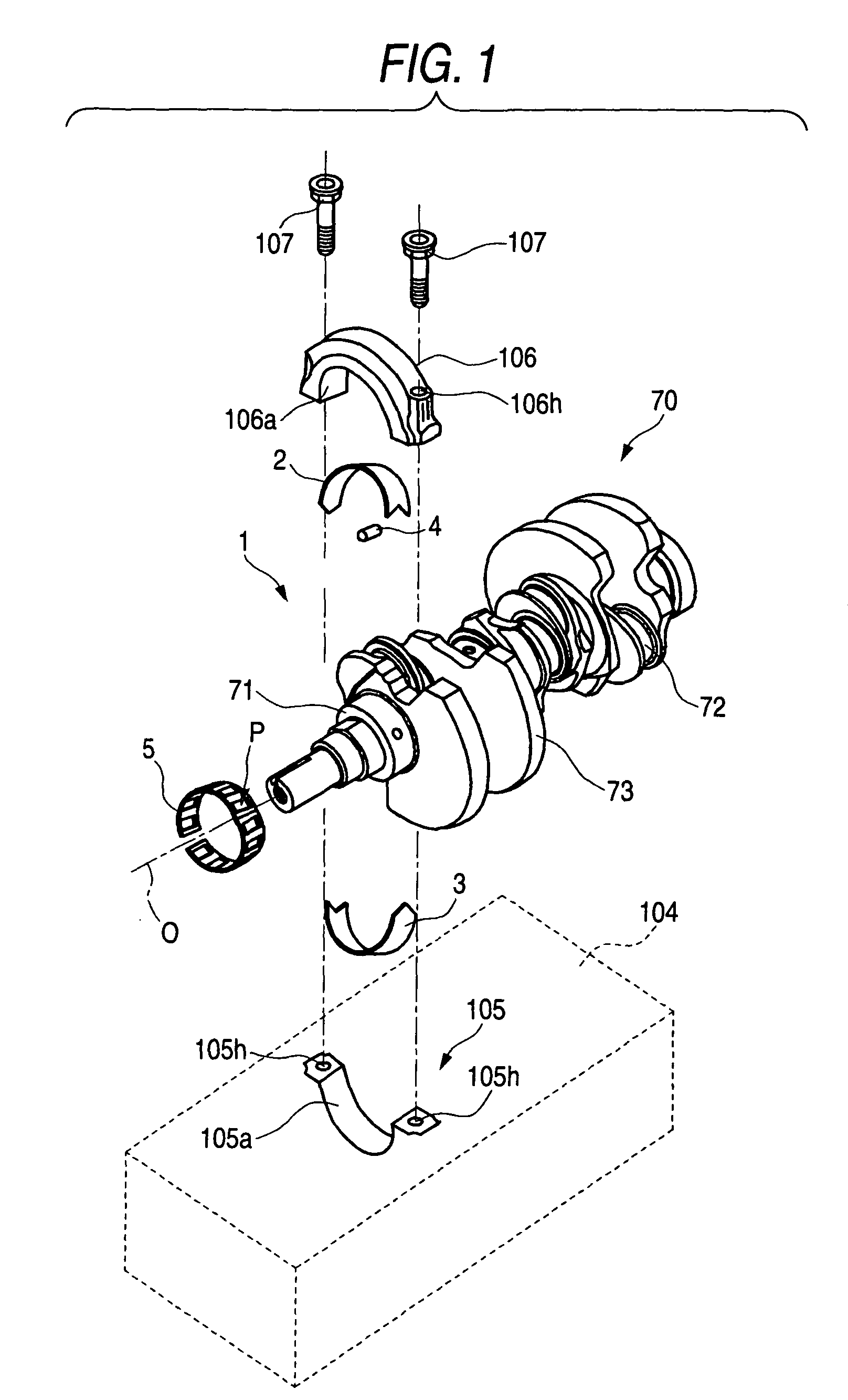
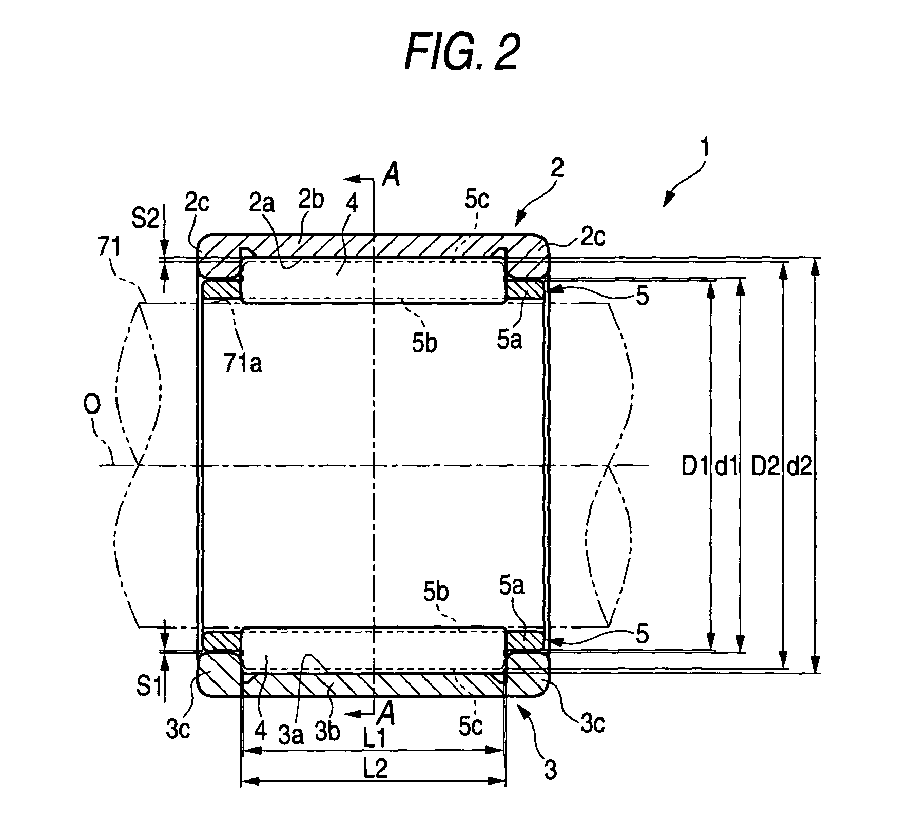
[0034]Hereinafter, embodiments of the invention are described with reference to the accompanying drawings. FIG. 1 is an exploded perspective view illustrating an example of a crankshaft having a roller bearing according to the intention. A crank journal 71 of a crankshaft 70 (corresponding to the rotating shaft) is put on a seat 105 (corresponding to the outer ring fixing member) formed integrally with a cylinder block (housing) 104 of an engine. The seat 105 and a cap member 106 (corresponding to the outer ring fixing member), which is disposed so as to upwardly face the seat 105 across the crank journal 71, are clamp-fixed to each other via a needle roller bearing (hereunder referred to simply as a roller bearing) 1. That is, the crank shaft 70 is rotatably supported by the roller bearing 1 on the cylinder block 104.
[0035]More specifically, paired internal thread holes 105h, and 105h are formed in the seat 105. Paired insertion holes 106h, and 106h are formed in the cap member 106...
embodiment 2
[0050]FIG. 5 is an exploded perspective view illustrating an example of a builtup cam shaft having a roller bearing according to the invention. A builtup camshaft 60 (corresponding to the rotating shaft) has a cam lobe 62 attachable and detachable from the direction of an axis line O. Thus, an integral type cage, which can not be circumferentially split, can be used as a cage 51 for a needle roller bearing (hereunder sometimes referred to simply as a roller bearing) 10.
[0051]A cam journal 61 of the builtup camshaft 60 is put on a seat 101 (corresponding to the outer ring fixing member) formed integrally with a cylinder block (housing) 100 of an engine. The seat 101 and a cap member 102 (corresponding to the outer ring fixing member), which is disposed so as to upwardly face the seat 101 across the cam journal 61, are clamp-fixed to each other via a roller bearing 10. That is, the builtup camshaft 60 is rotatably supported by the roller bearing 10 on the cylinder head 100.
[0052]More ...
PUM
 Abstract
Description
Claims
Application Information
 - R&D
- Intellectual Property
- Life Sciences
- Materials
- Tech Scout
- Unparalleled Data Quality
- Higher Quality Content
- 60% Fewer Hallucinations
Browse by: Latest US Patents, China's latest patents, Technical Efficacy Thesaurus, Application Domain, Technology Topic, Popular Technical Reports.
© 2025 PatSnap. All rights reserved.Legal|Privacy policy|Modern Slavery Act Transparency Statement|Sitemap|About US| Contact US: help@patsnap.com


