Atomizer monitoring system

a technology for monitoring systems and atomizers, applied in lighting and heating apparatus, instruments, furniture, etc., can solve the problems of affecting the quality of atomizers, so as to avoid the surprise failure of parts within an atomizer and/or the associated costly downtim

Inactive Publication Date: 2010-11-16
RPM SOLUTIONS
View PDF8 Cites 18 Cited by
  • Summary
  • Abstract
  • Description
  • Claims
  • Application Information

AI Technical Summary

Benefits of technology

[0008]The preferred embodiments include a system for monitoring parts that are utilized in machines (e.g., atomizers) for flue gas desulfurization or in spray drying applications, taking into account each part's longevity, installation date, and expiration period, using radio frequency identification (“RFID”) technology, whereby small, inexpensive RFID tags are placed on, or embedded in the atomizers, for example, in an atomizer wheel. The present invention accurately documents the wear life of components and provides information to precisely control inventories and scheduled maintenance events; which leads to the avoidance of the surprise failures of parts within an atomizer and / or the costly downtime associated with removal and replacement of parts that have not reached their useful life. At this juncture, it is important to mention that use of the parts monitoring system of the present invention is not limited to flue gas desulfurization. The system of the present invention may be used in a variety of other operating systems wherein multiple components are used having different lengths of wear life, wherein the wear life of those wear components cannot be determined, e.g., serial numbers cannot be viewed during normal operation, and there is no system in place for tracking wear life. Typically these type of applications would be for systems that have very long runtime between maintenance events. For example, the system of the present invention could be used for tracking parts in a coal pulverizer mill, large pumps or fans, turbines, etc.
[0013]The present invention can be distinguished from the prior art in several important ways. First, the present invention increases the safety of facilities where desulfurization or spray drying is carried out. Safety is an ongoing concern in all aspects of life, and coal fired power plants and spray drying facilities are no exception, especially with respect to the replacement of damaged or worn parts. Though many manufacturers use warning labels instructing users to replace damaged or worn parts only with the appropriate equivalent parts, there is no means of verifying such compliance. The exemplary embodiments of the present invention provide the benefit of enabling compliance verification and provide a tool for ensuring timely replacement.
[0014]Second, the exemplary embodiments of the present invention significantly enhance convenience. For example, modern coal fired power plants have many parts that require periodic replacement. The present invention, through constant verification, provides such a capability, enabling more accurate information to be provided to the user. These features are not contemplated or anticipated by the prior art.
[0015]The present invention reduces the amount of paperwork involved with tracking numerous parts that make up the multiple atomizer wheels located within a coal-fired power plant, waste-to-energy plants and in incinerators, by tracking these parts using radio frequency identification tags and a computerized monitoring system. The present invention also enables one to determine a cost for use of an atomizer wear part based upon the initial cost of the part and the length of service of that part before that part is considered worn out. In addition to cost per unit comparisons, under the present invention, the life of atomizer wear parts can be correlated to the amount of slurry used, the amount of lime used or the amount of sulfur removed. Many sets of data may be monitored during the operation of the atomizer and then compared to the operational wear life of any of the atomizer parts that are being tracked by the atomizer monitoring system. The present invention is a budget / inventory management tool.
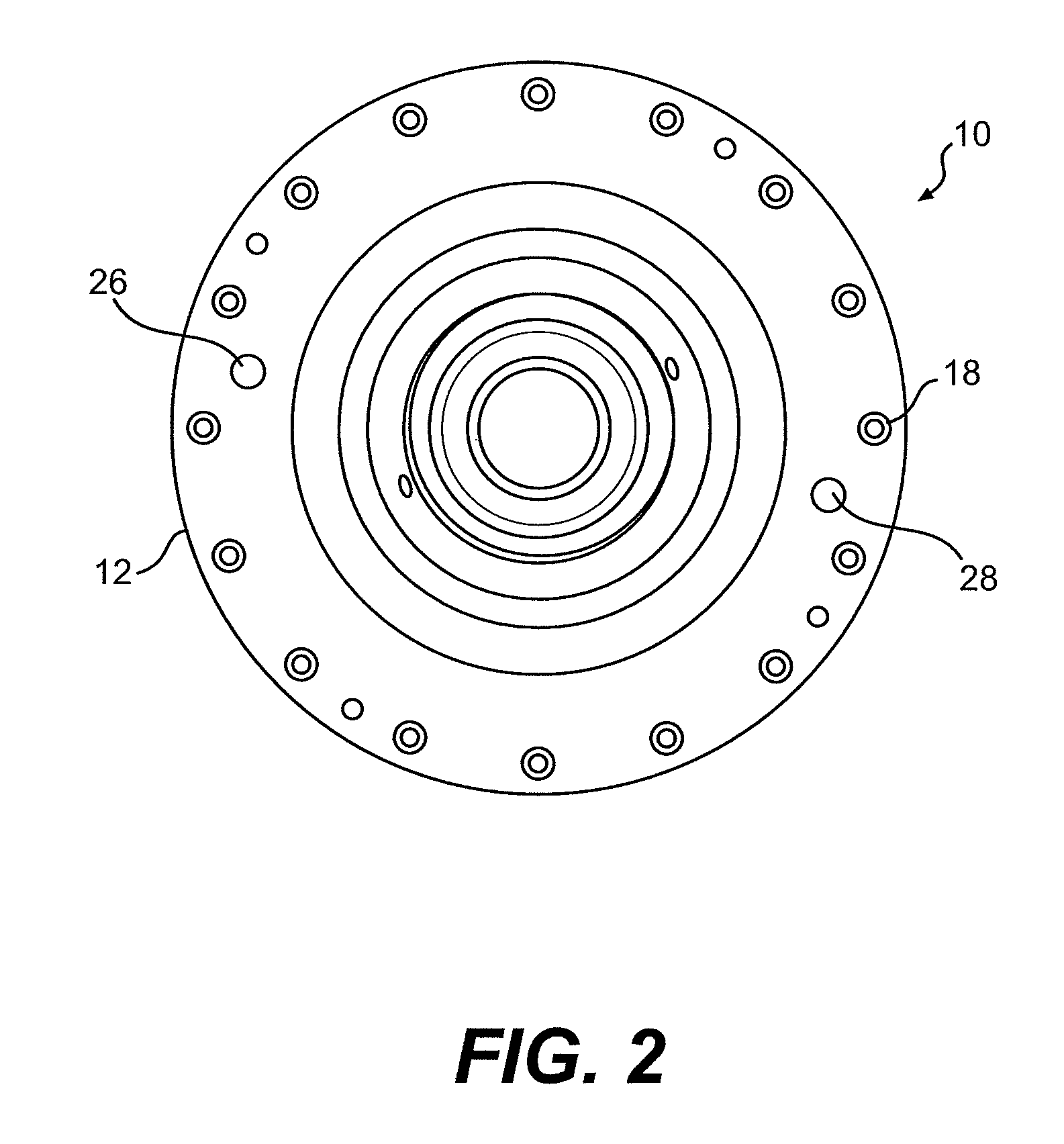
[0017]The exemplary embodiments provide a system and method for gathering data concerning parts within atomizer wheels of a coal fired power plant, or other complex structures such as a spray drying facility which is comprised of multiple mechanical parts, and using that data to determine whether the parts are the appropriate parts for use in that structure and for indicating when parts need to be replaced so as to increase the operational efficiency and safety of the structure. The system uses RFID technology to initially associate data from different parts and to facilitate the identification of those parts in the future. In particular, small, relatively inexpensive RFID tags are placed on, or embedded in, various different parts of the structure. In the context of an atomizer wheel located within a coal fired power plant, although numerous different parts could be labeled with RFID tags, the preferred embodiment of the present invention is primarily focused on placing an RFID tag on the chamber in which one or multiple atomizer wheels are located, embedding RFID tags in the lid of each atomizer wheel housed within each chamber, and placing RFID tags on other parts of the atomizer including the atomizer motor and gearbox assembly. Preferably any of the tags allow the association of data with numerous different parts of the atomizer, thereby lowering the need for a separate tag for each part, as discussed for example in greater detail below.

Problems solved by technology

This is a laborious task and time consuming.
Keeping track of the existence and / or status of hundreds of parts within a group of atomizer systems is not only a complex task, but virtually impossible with currently available systems.
Taking inventory of any type of article is a time-consuming and difficult task that must be done in all industries.
However, these systems suffer from significant limitations, including a line-of-sight requirement for accurate readings, no permanency for marking part numbers which often wear away, space limitations on parts for marking identification numbers, parts being made of materials unsuitable for marking due to surface characteristics and part numbers concealed during use with other parts.
Inspection of atomizer parts is both inefficient and risky, requiring separation and reassembly of numerous assemblies within the atomizer, which may affect tolerances and operability of the reconstructed assemblies over time.

Method used


Image

  • Atomizer monitoring system
  • Atomizer monitoring system
  • Atomizer monitoring system

Examples


Embodiment Construction

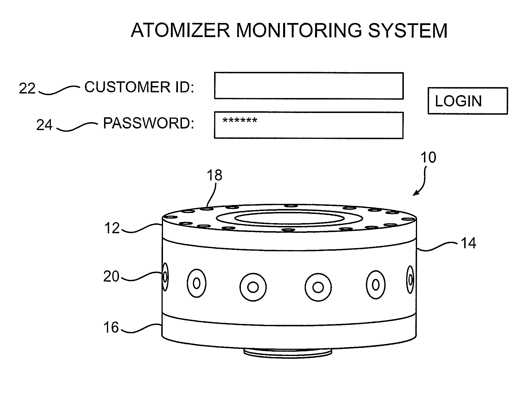
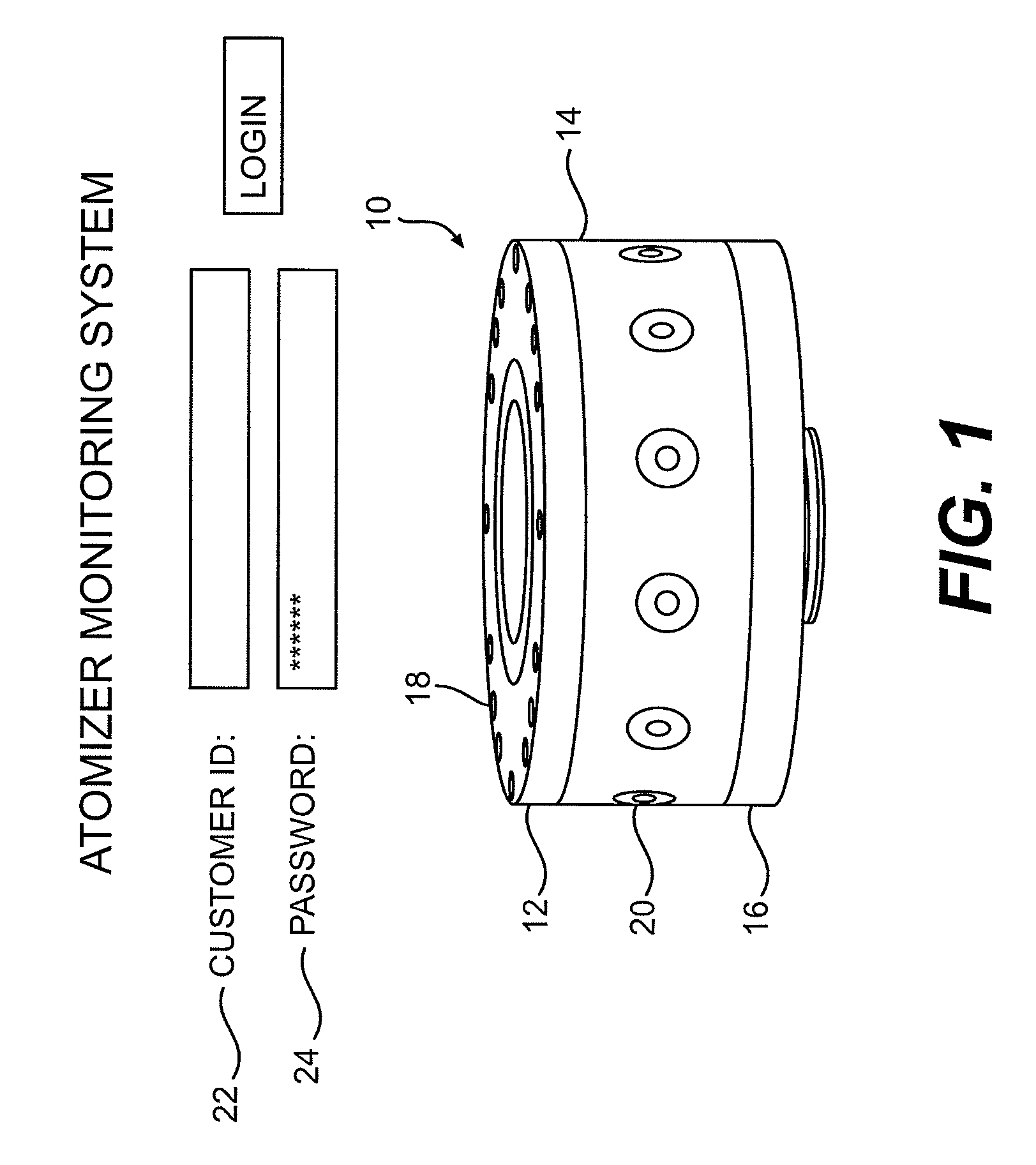
[0029]Referring now in detail to the various figures of the drawings wherein like reference characters refer to like parts, there is shown in FIG. 1 a prospective view of an atomizer wheel 10 having a lid 12, a case 14 and a drive plate 16. The lid 12 and case 14 are attached via threaded head cap screws 18 that are inserted into the lid and threadingly engage the case. Typically the atomizer wheel 10 includes a plurality of wear inserts 20 positioned within ejection orifices located on the circumference of the sidewall of the case 14. While not being limited to a particular theory, during operation the atomizer wheel 10 rotates at very high speeds and multiple atomizer wheels may be located within a processing or treatment chamber where flue gases are subjected to desulfurization treatment within a flue gas desulfurization system of a coal fired power plant or incinerator. The atomizer wheel 10 preferably also includes, wear rings, wear nuts, lids, cases, lower drive plates, o-ring...


PUM

PropertyMeasurementUnit
diameteraaaaaaaaaa
timeaaaaaaaaaa
timeaaaaaaaaaa

Abstract

An atomizer monitoring system monitors parts or components that are utilized in atomizers for flue gas desulfurization or in spray drying applications, taking into account each part's longevity, installation date, and expiration period, using wireless sensors and radio frequency identification (“RFID”) technology, whereby small, inexpensive RFID tags are placed on, or embedded in the atomizers, for example, in an atomizer wheel. The monitor system can avoid failure of parts within an atomizer and costly downtime associated with removal and replacement of parts that have reached their useful life. The preferred embodiment utilizes radio frequency identification (“RFID”) technology which is linked to a web-based data base.

Description

CROSS-REFERERENCE TO RELATED APPLICATIONS[0001]This application is a nonprovisional application of U.S. Provisional Application No. 60 / 807,841, still pending, filed Jul. 20, 2006.FIELD OF INVENTION[0002]This invention relates to the monitoring of parts, and in particular, to the monitoring of parts that are utilized in atomizers for flue gas desulfurization or in spray drying applications.BACKGROUND OF THE INVENTION[0003]Flue gas desulfurization systems are typically used in coal fired power plants, waste-to-energy plants and in incinerators. A typical desulfurization system will include a processing or treatment chamber wherein flue gases are subjected to desulfurization treatment. Positioned inside that chamber is a high speed rotating atomizer wheel through which desulfurization treatment slurry is dispersed into the chamber and the gas therein in order to initiate the desulfurization process. Typically, the atomizer wheels are circular with a circumferential sidewall that includ...

Claims


Application Information

Patent Timeline
Patent Type & Authority Patents(United States)
IPC IPC(8): G01N17/00
CPCB05B12/00F26B3/12B05B15/18
Inventor MUDGE, ROBERT P.VEURINK, SHAWN M.
Owner RPM SOLUTIONS
Why Eureka
Try Eureka