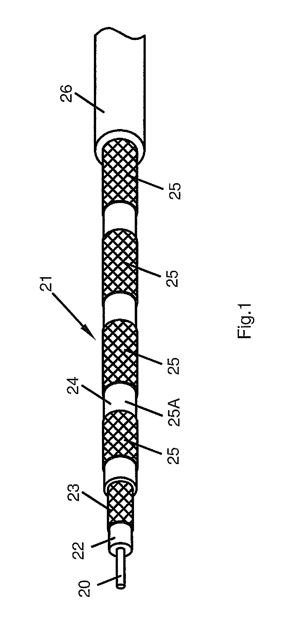
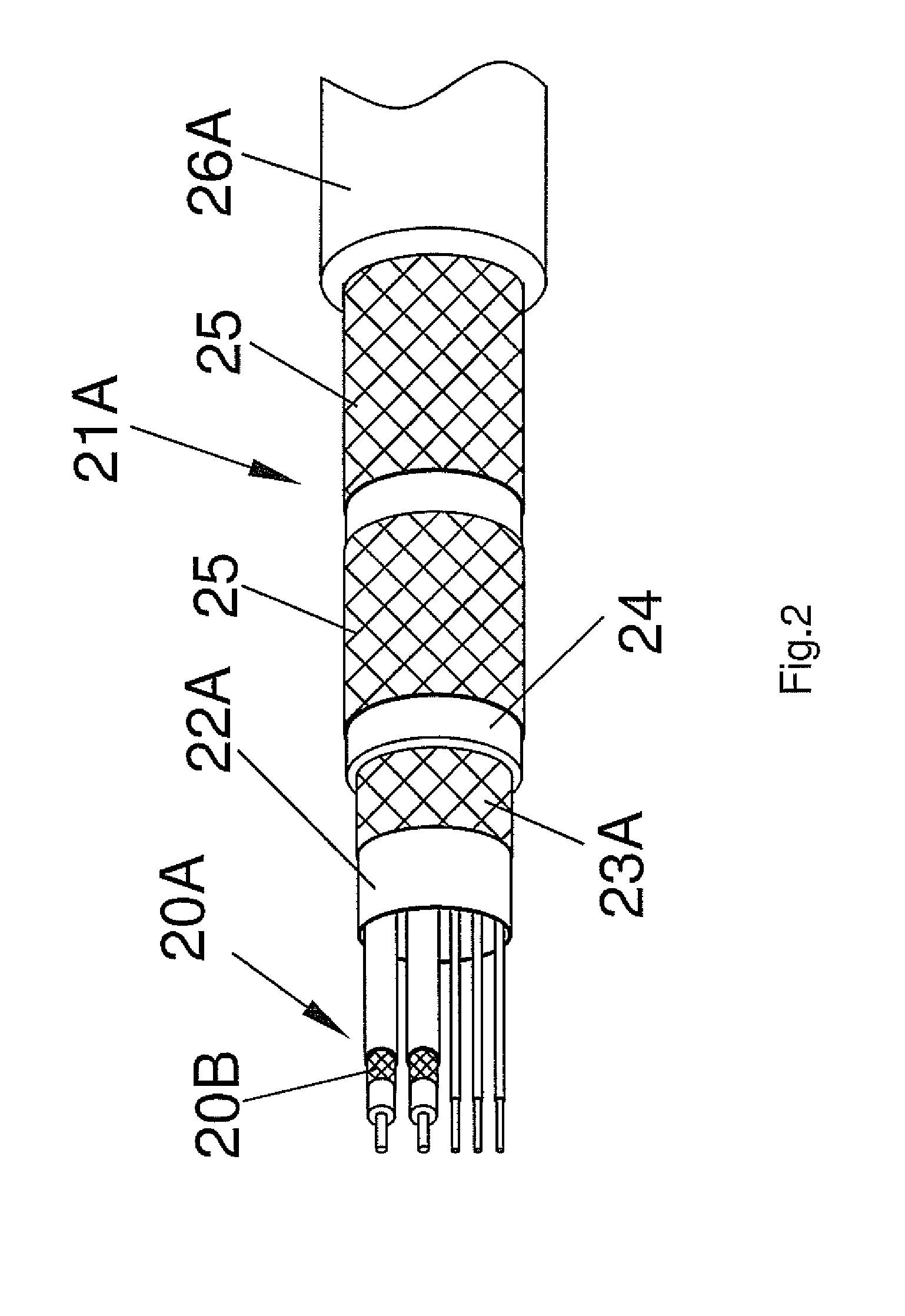
Floating segmented shield cable assembly

a shield cable and segmented technology, applied in power cables, conductors, electrical devices, etc., can solve the problems of affecting the creation of the homogenous rf field generated by the transmit body, affecting the image quality, and affecting the heating or burn of patients

Inactive Publication Date: 2010-11-16
DEERFIELD IMAGING INC
View PDF9 Cites 97 Cited by
  • Summary
  • Abstract
  • Description
  • Claims
  • Application Information

AI Technical Summary

Benefits of technology

[0023]It is one object of the invention to provide a cable for communicating signals in an RF field where the creation of currents in the cable by the RF field is reduced.

Problems solved by technology

These currents, and the resulting heat produced, can cause serious patient heating or burns.
Common mode currents also degrade the image quality by affecting coil tuning, coil-to-coil coupling in phased array coils.
In addition the generation of currents in the shield of cables within the coil, especially cables close to or crossing the individual coil loops in a phased array coil, in the magnetic field of the MR scanner can interfere with the creation of the homogenous RF field generated by the transmit body coil.
This inhomogeneity of the RF field can generate artifacts within the image obtained.
Such contact, however, is unavoidable in many cases such as when using ECG cables, surface coils, or intra-cavity coils.
This design decreases the unbalanced currents on the coaxial cable.
Similar and more serious problems exist for the coils that are inserted inside the body such as endorectal, esophageal, and intravascular RF probes.
As these devices are closer to the body, the risk of localized heating or burning a patient is increased.
In this case the high number of cable traps required in the intra-operative MRI coil signal transmission cable in conjunction with the great length of the cable makes the cable particularly unwieldy.
This type of cable trap increases the overall coil and cable weight and is not convenient for handling in a surgical setting.
Also the additional length of the raw cable required, when wrapped helically, to form a cable trap negatively affects the RF chain.

Method used


Image

  • Floating segmented shield cable assembly
  • Floating segmented shield cable assembly
  • Floating segmented shield cable assembly

Examples


Embodiment Construction

[0091]In FIG. 6 is shown schematically a magnetic resonance imaging system which includes a magnet 10 having a bore 11 into which a patient 12 can be inserted on a patient table 13. The system further includes an RF transmit body coil 14 which generates a RF field within the bore.

[0092]The system further includes a receive coil system generally indicated at 15 which is located at the isocenter within the bore and receives signals generated from the human body in conventional manner. A RF control system 17 acts to control the transmit body coil 14 and to receive the signals from the receive coil 15. The cable 16 must be draped into the bore alongside the patient to connect to the received coil assembly within the bore.

[0093]In FIG. 7 is shown schematically the receive coil assembly 15 which in this arrangement includes a plurality of received coil loops 15A, 15B, 15C and 15D. Each of these loops is connected to a signal transmit coaxial cable and control wire bundle portion 16A, 16B,...


PUM

PropertyMeasurementUnit
lengthaaaaaaaaaa
lengthaaaaaaaaaa
lengthaaaaaaaaaa

Abstract

Signals in an RF field, such as that of an MRI system, are communicated through an inner conductor having an outer shield with a dielectric material therebetween and an outer cable jacket. Current in the shield caused by the RF field from the transmit body coil is reduced by providing a second dielectric material around the shield conductor and a plurality of segmented shield conductor portions formed of non-magnetic braid or wrapped non-magnetic foil tape outside the second dielectric material and inside the jacket at spaced positions along the cable, with the portions being electrically separated from each other and from the shield so that the segmented shield conductor portions act to shield the outer shield conductor to reduce the generation of current thereon while the electrical separation of the segmented shield conductor portions each from the others prevents the generation of a current along the portions.

Description

[0001]This invention relates to coaxial cables for use in high RF fields where currents induced in the shield of the cable can have deleterious effects. The invention is particularly applicable to such cable when used in the high RF fields used in Magnetic Resonance Imaging but can relate to other cables. The invention also includes a jacket arrangement which can be applied on to a conventional coaxial cable to obtain the advantageous construction described herein.BACKGROUND OF THE INVENTION[0002]Many coaxial cables are required to be used in the high RF fields used in MRI. These include primarily the cables to the receive coil array but also other cables that must enter the high RF field such as those used in pacemakers, ECG testing, electrophysiology and EEG monitoring, and Deep Brain Stimulation systems (DBS).[0003]Common mode signals or shield currents on coil cables are often caused by the coil itself or by an external source such as a surrounding transmit body coil during tran...

Claims


Application Information

Patent Timeline
Patent Type & Authority Patents(United States)
IPC IPC(8): H01B9/02
CPCH01B11/1895
Inventor ZHU, HAOQINLI, JONATHANSAUNDERS, JOHN K.
Owner DEERFIELD IMAGING INC
Why Eureka
Try Eureka