Bearing assembly

a technology of bearings and components, applied in the direction of elastic bearings, rigid supports of bearings, mechanical devices, etc., can solve problems such as bearing deformation, and achieve the effect of reducing their lifetim

Inactive Publication Date: 2010-11-16
DYSON TECH LTD
View PDF24 Cites 8 Cited by
  • Summary
  • Abstract
  • Description
  • Claims
  • Application Information

AI Technical Summary

Benefits of technology

[0013]The invention is suitable for supporting rotor assemblies comprising a rotor on a shaft. Preferably, the bearing assemblies are located at both ends of the shaft. Resilient means may be provided on the housings to permit the rotor assembly to rotate a

Problems solved by technology

A problem which may be encountered with conventional bearing assemblies is that the press

Method used


Image

  • Bearing assembly
  • Bearing assembly
  • Bearing assembly

Examples


Embodiment Construction

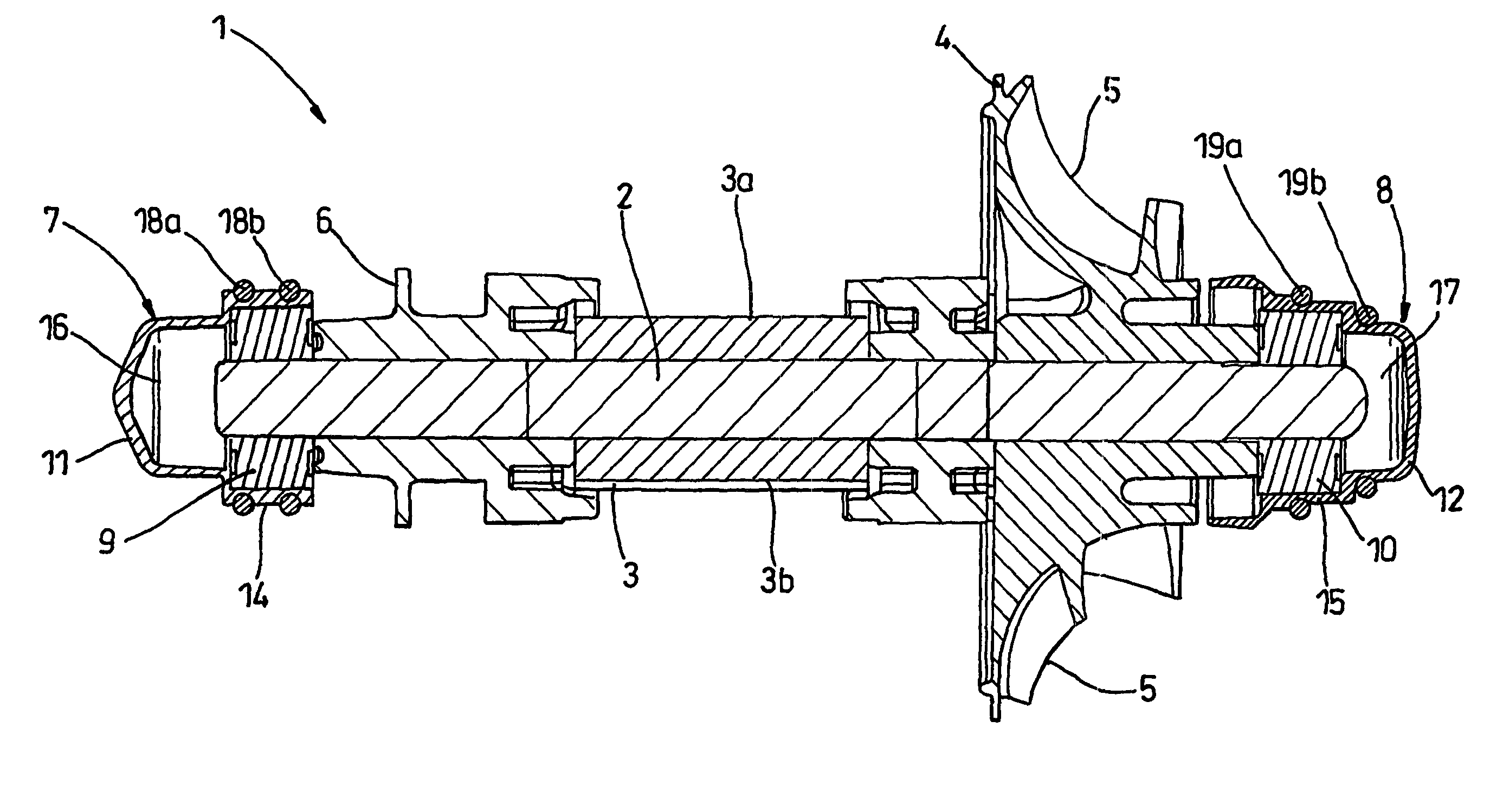
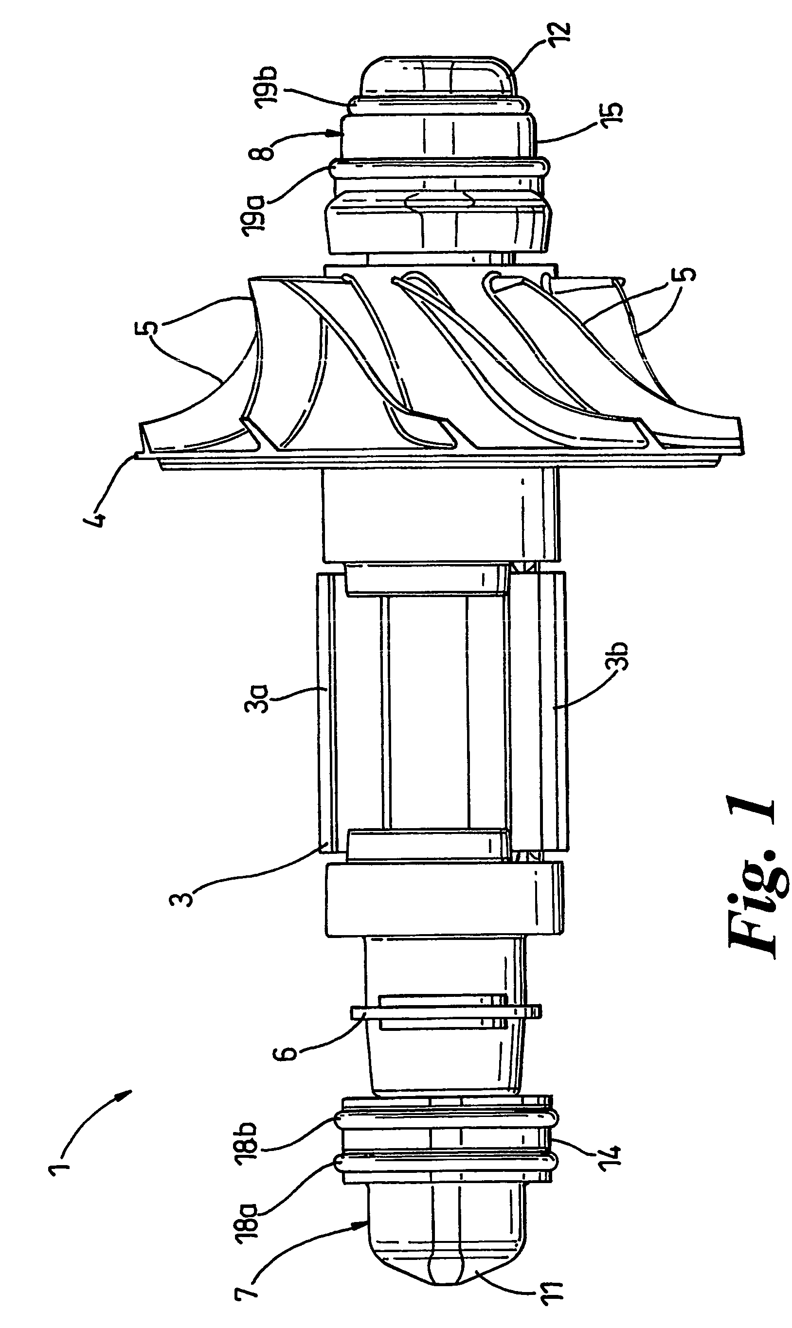
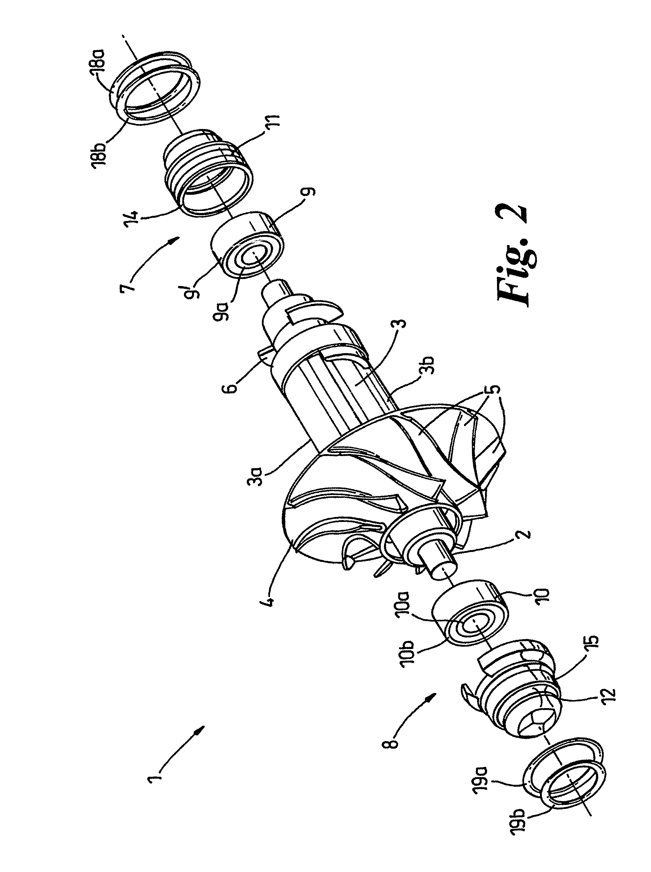
[0024]FIGS. 1 to 3 show a rotor assembly indicated generally by the reference numeral 1. The rotor assembly 1 comprises a rotor shaft 2 having a rotor member 3. The rotor member 3 comprises an axially laminated stack of steel plates, arranged to form a pair of poles 3a, 3b. The shaft 2 also carries a coaxial impeller 4 having a plurality of blades 5 arranged to direct fluid flow from the shaft to the periphery of the impeller in tangential directions. The shaft also carries a pair of balance rings and a position indicator in the form of an optical encoder disc 6, to enable the rotational position of the rotor member 3 to be determined in use.

[0025]Bearing assemblies 7, 8 are provided on the shaft 2. Each bearing assembly 7, 8 comprises a bearing 9, 10 supported on the shaft 2 by a housing 11, 12. The bearings 9, 10 are arranged to press-fit into their respective housings 11, 12 and also to press-fit onto the rotor shaft 2. Each bearing 9, 10 comprises an inner race 9a, 9b, an outer ...


PUM


Abstract

A bearing assembly particularly suitable for the rotor arrangement of an electrical motor or generator includes a bearing located in a housing. The bearing has an inner race, an outer race, and a plurality of ball bearings between the inner and outer races. A portion of the housing is made up of a deformable flexible wall which permits the housing to conform to the shape of the outer race member, rather than forcing the outer race to conform to the shape of the housing, as was experienced hitherto.

Description

FIELD OF THE INVENTION[0001]This invention relates to a bearing assembly for, for example, the rotor of an electrical machine such as an electrical motor or generator.BACKGROUND OF THE INVENTION[0002]Electrical motors are widely used for many different applications and are commonly used in domestic appliances. For example, in a vacuum cleaner a motor is used to drive a fan that causes dirty air to be sucked through a dirty air inlet. The dirty air passes through some form of separation device such as a cyclonic or bag separator that separates dirt and dust from the airflow, and finally the air is exhausted from an air outlet.[0003]Switched reluctance machines have become increasingly popular in recent years. In a switched reluctance motor, a stator has sets of poles that are sequentially energised to rotate a rotor into line with the energised pair of poles, under the influence of the magnetic fields associated with each set of poles. By rapidly switching between different pairs of ...

Claims


Application Information

Patent Timeline
IPC IPC(8): H02K7/08F16C27/04F16C27/06F16C35/04F16C35/077H02K5/173H02K7/14
CPCF16C27/066F16C35/077H02K5/1732H02K7/14F16C2314/00F16C2360/44F16C35/04
Inventor CHILDE, MATTHEW JOHNCROSSLEY, PETER LEE
Owner DYSON TECH LTD
Why Eureka
Try Eureka