

Plasma display panel and method of producing the same
a technology of plasma and display panel, which is applied in the manufacture of electrode systems, cold cathode manufacturing, and electric discharge tube/lamp manufacture, etc., can solve the problems of inferior blue luminance or inferior chromaticity of pdp produced using glass, yellowing and other problems, and achieve high reliability and high withstand voltage
- Summary
- Abstract
- Description
- Claims
- Application Information
AI Technical Summary
Benefits of technology
Problems solved by technology
Method used
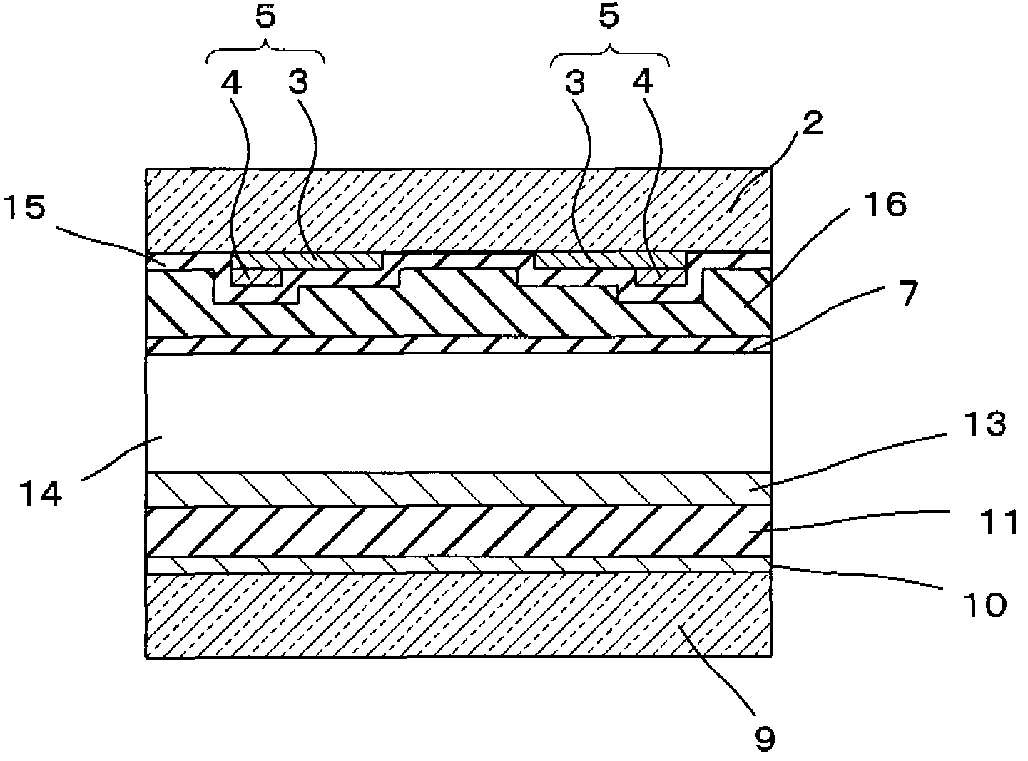
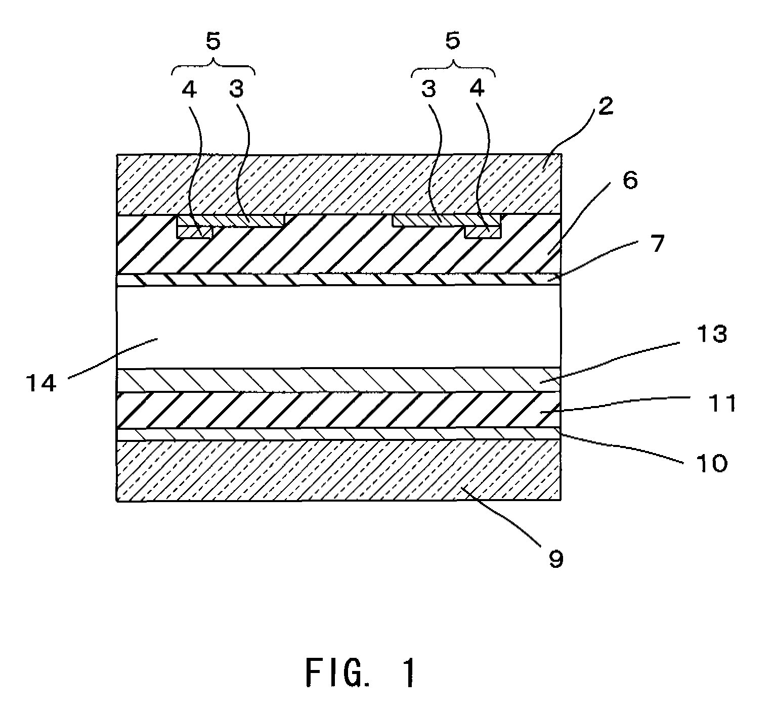
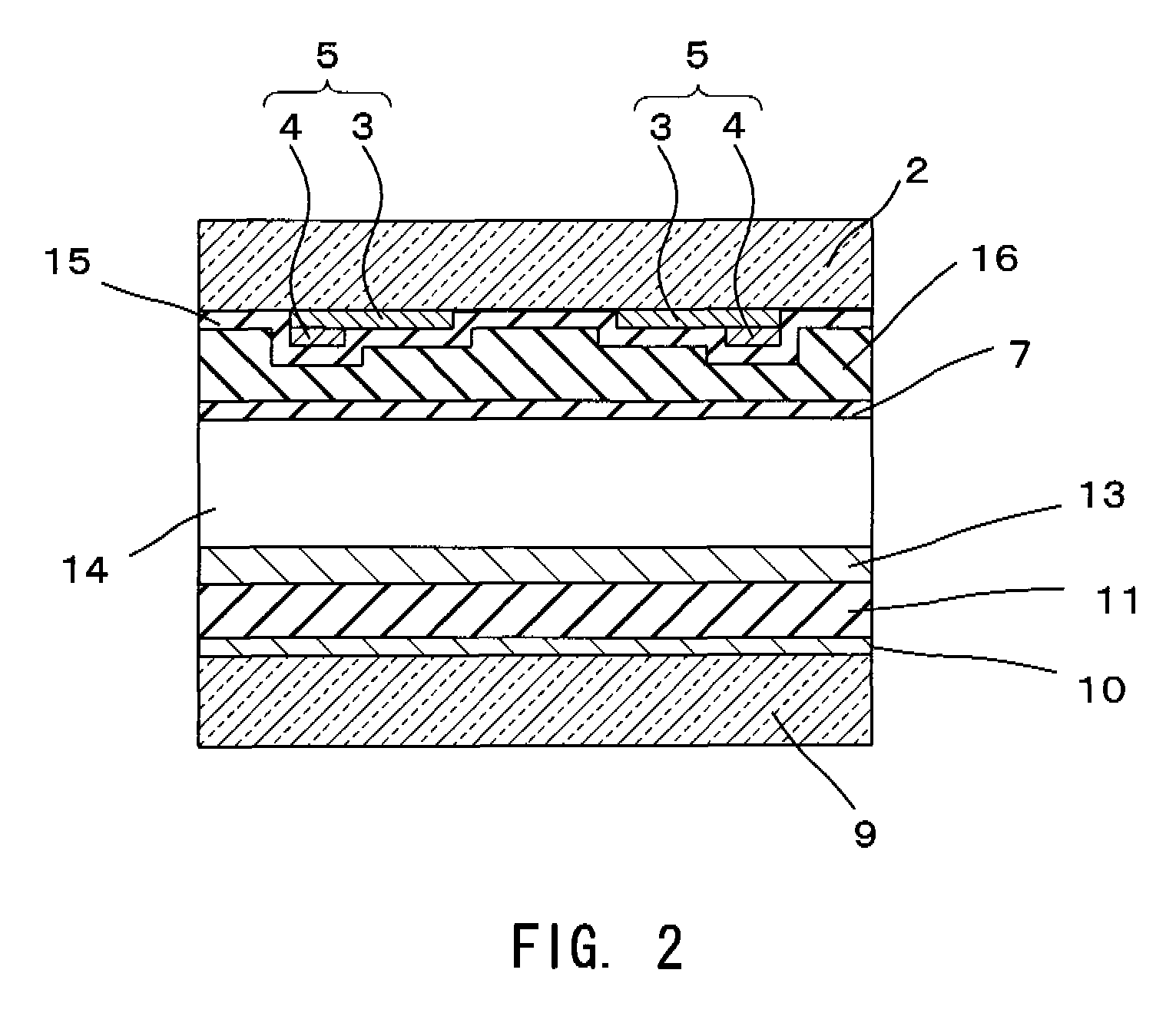
Image

Examples
examples
[0126]Hereafter, the present invention is described further in detail using examples.
[0127]Glasses that are used for dielectric layers of PDPs of the present invention were produced. The compositions of the glasses (Samples 1 to 36) of the examples that are suitably used for dielectric layers of PDPs of the present invention are indicated in Tables 1 to 4, and the compositions of the glasses (Sample 101 to 121) are indicated in Tables 5 to 7. In the tables, “SiO2” is indicated as “SiO2”, for example.
[0128]
TABLE 1GlassComposition / No.12345678910SiO215.09.71.014.99.312.01.61.5B2O327.329.530.910.015.050.024.230.623.426.9ZnO27.026.826.033.635.726.015.031.839.750.0Al2O30.32.71.70.73.20.75.10.81.11.3Bi2O323.216.011.028.319.79.521.113.712.48.1MgO1.2CaO5.516.95.41.35.52.6SrO1.24.12.2BaO6.45.610.55.612.513.721.019.710.18.4Li2ONa2O1.3K2OMoO30.83.02.00.10.60.52.00.5WO30.30.51.03.0Glass492493485491492469491477480473TransitionPoint(° C.)Softening593589581590588572598574576569Point(° C.)Thermal646...
PUM
| Property | Measurement | Unit |
|---|---|---|
| temperature | aaaaa | aaaaa |
| wt % | aaaaa | aaaaa |
| pressure | aaaaa | aaaaa |
Abstract
Description
Claims
Application Information