Method of forming a hardened skin on a surface of a molded article
a technology of hardened skin and molded articles, which is applied in the field of flow molding, can solve the problems that the hardened skin is not desired on the top surface of the molded article, and achieve the effect of convenient washing
- Summary
- Abstract
- Description
- Claims
- Application Information
AI Technical Summary
Benefits of technology
Problems solved by technology
Method used
Image
Examples
example 1
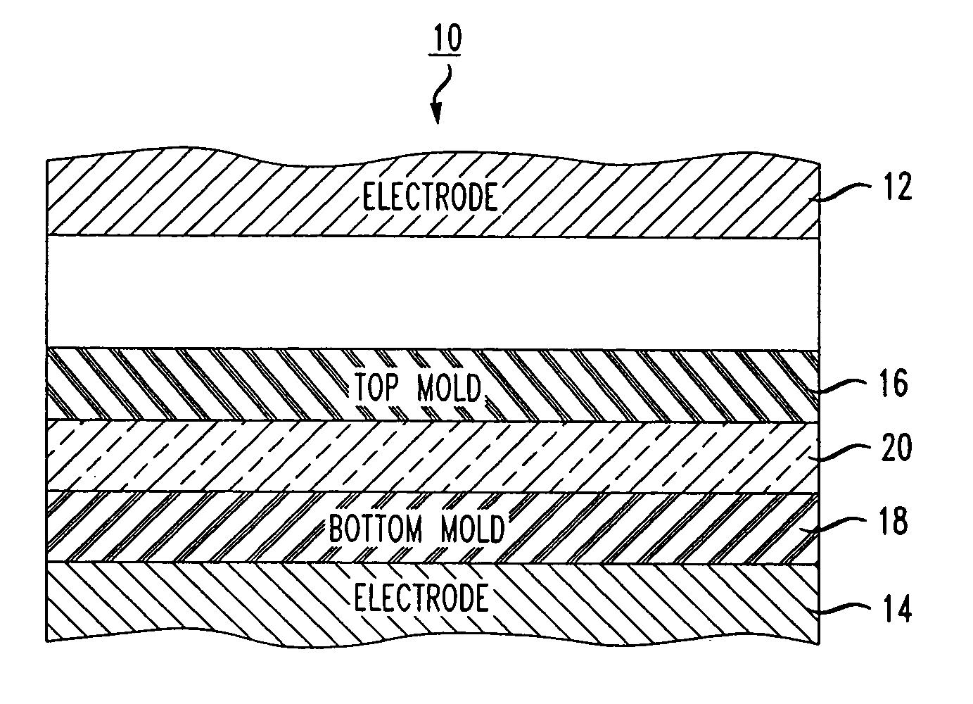
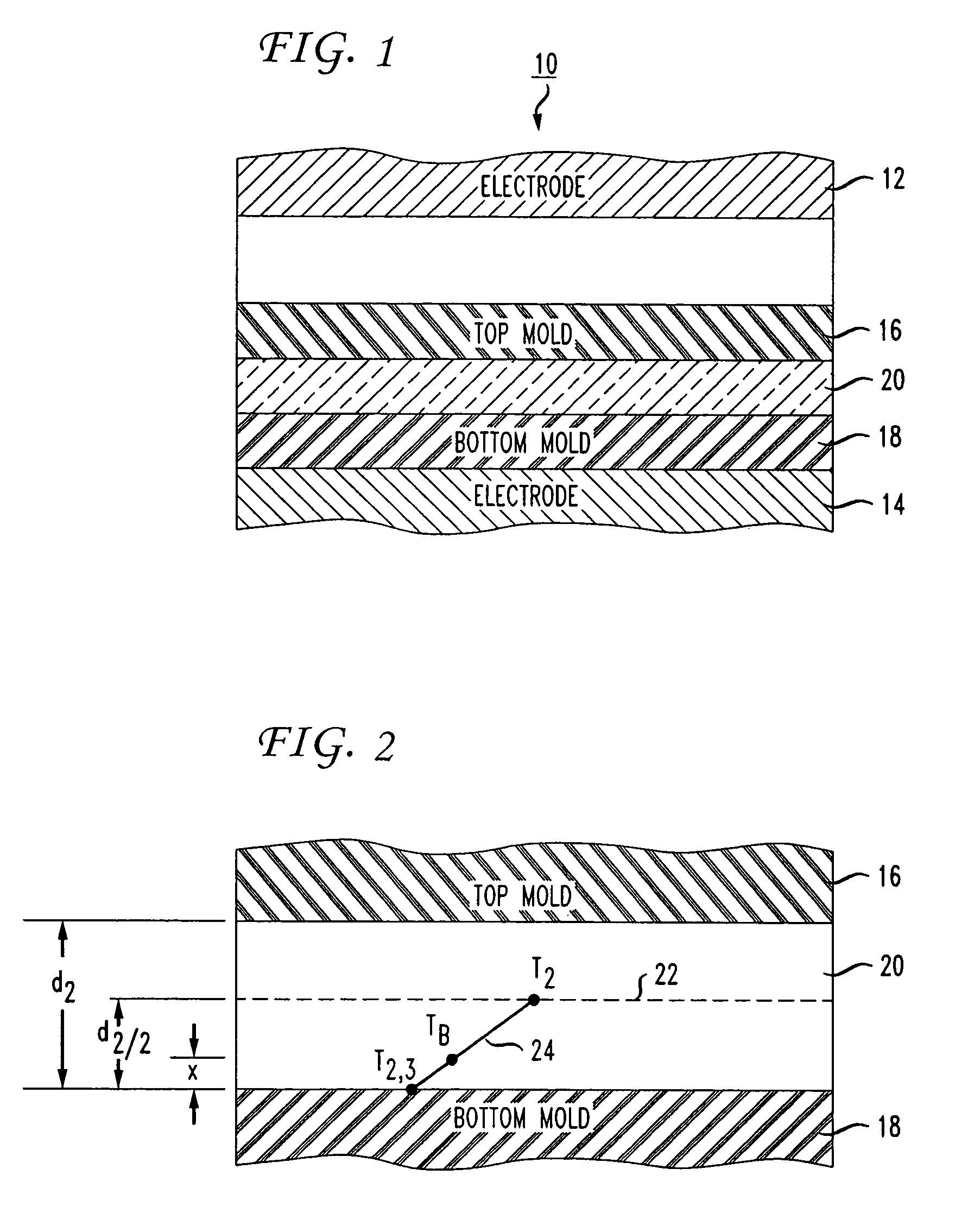
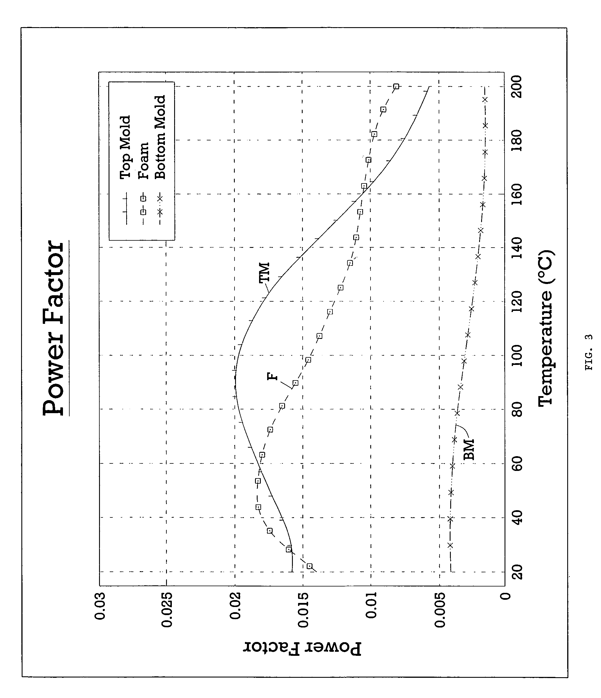
[0154]Assume for purposes of this example that top mold 16 and bottom mold 18 of flow molding apparatus 10 are each formed from silicone rubber V-1008 (manufactured by Rhodia Inc.) and foam material 20 comprises an EVA foam blend. Table 1 is provided below to show various factors for each of these layers of material, namely, the desired temperature (T) at the end of the heating cycle, thickness (d), power factor (pf), relative dielectric constant (∈), specific heat (h), and specific gravity (ρ). These factors will be used hereinbelow to perform various calculations in accordance with the method of the present invention.
[0155]
TABLE 1FoamTop MoldMaterialBottom Mold(layer 1)(layer 2)(layer 3)Desired200200Temperature (T)(degrees Celsius)Thickness (d).125.375.125(inches)Power Factor (pf).0137.0033Relative Dielectric3.072.672.67Constant (ε)Specific Heat (h)1.2331.5661.233Specific Gravity (ρ)1.161.0411.16
[0156]As can be seen from Table 1, the desired temperature of foam material 20 at the ...
example 2
[0186]Assume for purposes of this example that bottom mold 18 is formed from silicone rubber V-1075 (manufactured by Rhodia Inc.), which contains iron oxide and thus has a higher thermal conductivity than the silicone rubber V-1008 used in Example 1. Specifically, the thermal conductivity of silicone rubber V-1075 is 0.0241. All of the calculations and values of Example 1 remain unchanged, with the exception of the following analysis.
[0187]The temperature at the interface between foam material 20 and bottom mold 18 may be calculated from equation (19) using the temperature (T3) of bottom mold 18 derived in Example 1 above and the value for the temperature (T2) of foam material 20 shown in Table 1 (assuming that the thermal conductivity of foam material 20 is still 0.00638 while the thermal conductivity of bottom mold 18 is now 0.0241):
[0188]T2,3=(.00638×200)+(.0241×55.48).00638+.0241=85.73°C.
[0189]Thus, the temperature at the interface between foam material 20 and bottom mold 18 ...
example 3
[0197]In this example, equation (25) (which is a combination of equations (8) and (24)) will be used to calculate more exact values for the molding time (t2) of foam material 20, the temperature (T3) of bottom mold 18, and the thickness (x) of foam material 20 that remains under the decomposition temperature (TB) of the blowing agent (as compared to the values calculated in Example 1 above). It should be understood that the subscripts used in the following equations denote the layer number of the particular material (i.e., subscript 1 denotes top mold 16 (layer 1), subscript 2 denotes foam material 20 (layer 2), subscript 3 denotes bottom mold 18 (layer 3), and subscript 4 denotes bottom electrode 14 (layer 4)).
[0198]The power (P2) that is dissipated in foam material 20 due to the application of the dielectric field may be calculated from equation (8) using the current (I) and capacitance (C2) derived in Example 1 above and the value for the power factor (pf2) shown in Table 1 (assu...
PUM
| Property | Measurement | Unit |
|---|---|---|
| frequencies | aaaaa | aaaaa |
| frequencies | aaaaa | aaaaa |
| frequencies | aaaaa | aaaaa |
Abstract
Description
Claims
Application Information
 - R&D
- Intellectual Property
- Life Sciences
- Materials
- Tech Scout
- Unparalleled Data Quality
- Higher Quality Content
- 60% Fewer Hallucinations
Browse by: Latest US Patents, China's latest patents, Technical Efficacy Thesaurus, Application Domain, Technology Topic, Popular Technical Reports.
© 2025 PatSnap. All rights reserved.Legal|Privacy policy|Modern Slavery Act Transparency Statement|Sitemap|About US| Contact US: help@patsnap.com


