Hand-held fluid analyzer
a fluid analyzer and hand-held technology, applied in the field of dispensing, can solve the problem that the reduced-diameter ampoule cannot be positioned within the housing, and achieve the effect of facilitating visual observation of color changes and enhancing the ability of users to visually
- Summary
- Abstract
- Description
- Claims
- Application Information
AI Technical Summary
Benefits of technology
Problems solved by technology
Method used
Image
Examples
first embodiment
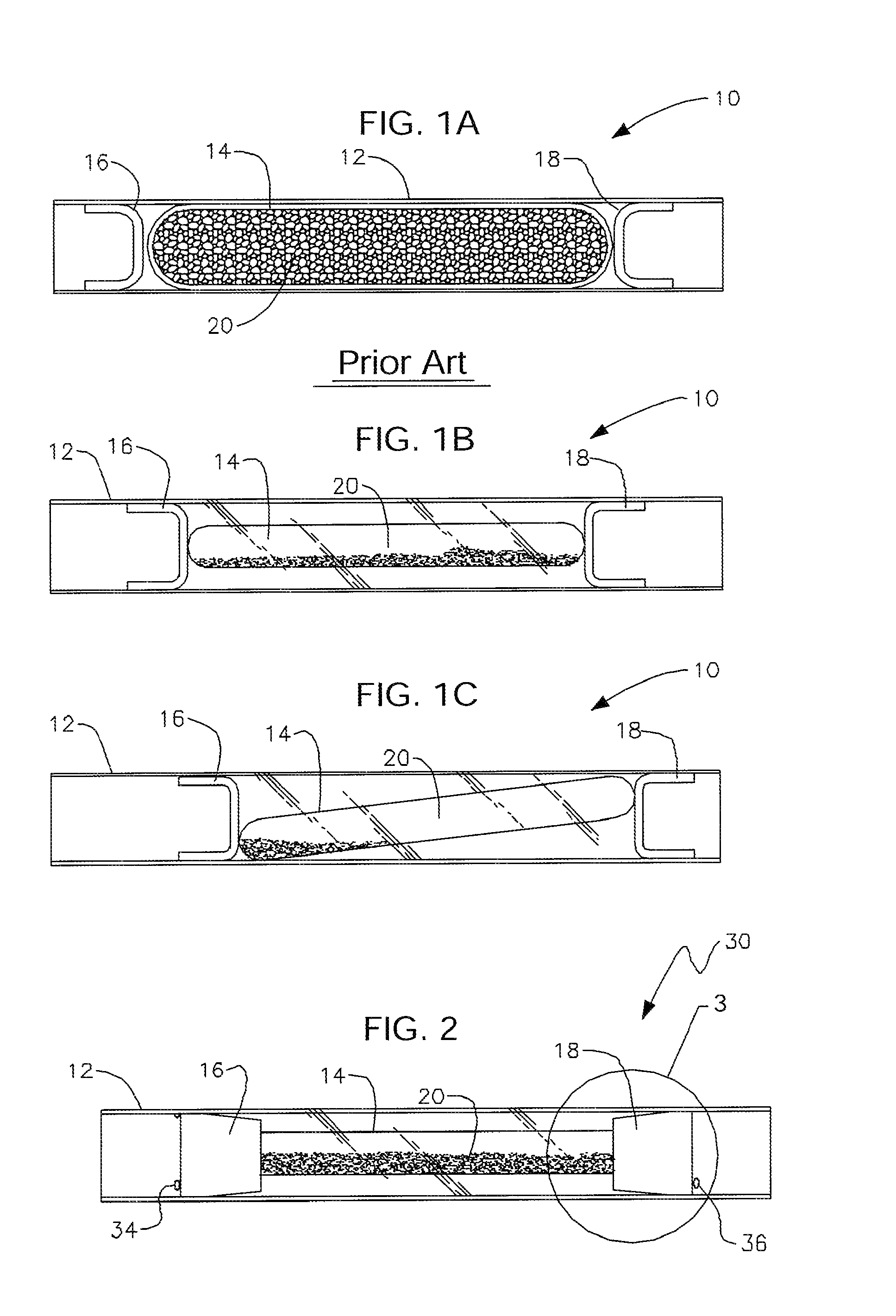
[0109]FIG. 1B depicts this invention. The diameter of glass ampoule 14 is reduced so that space is provided between vinyl housing 12 and glass ampoule 14. Thus, there is an increased measure of protection from glass shards, as compared to the patented embodiment of FIG. 1A. Moreover, ampoule 14, in the improved embodiment of FIG. 1B, is no longer completely filled. Instead it is about half full to make it easier to blow through detector 10 when ampoule 14 has been broken.
[0110]However, as indicated in FIG. 1C, one or both of the filters at the opposite ends of the reduced-diameter ampoule of FIG. 1B may slip from their initial positions, allowing ampoule 14 to become tilted, or canted, within the substance detector housing. When this occurs, the tilt of the ampoule causes the chemical grains therewithin to tend to accumulate toward one end of the ampoule. If the accumulation becomes excessive, it can alter the effectiveness of the indicator.
[0111]Moreover, when ampoule 14 is oblique...
second embodiment
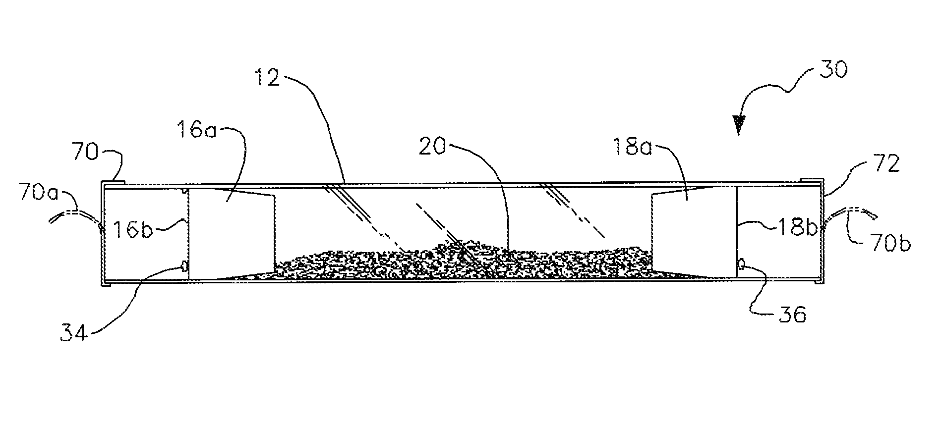
[0118]The canted-ampoule problem is resolved by this invention, denoted as a whole by the reference numeral 30 in FIG. 2. The longitudinal axis of symmetry of ampoule 14 is coincident with a longitudinal axis of symmetry of housing 12, with the result that indicator reagent 20 is evenly distributed within ampoule 14, even though the amount of said indicator reagent is only about half of the amount used in prior art detector 10 of FIG. 1A.
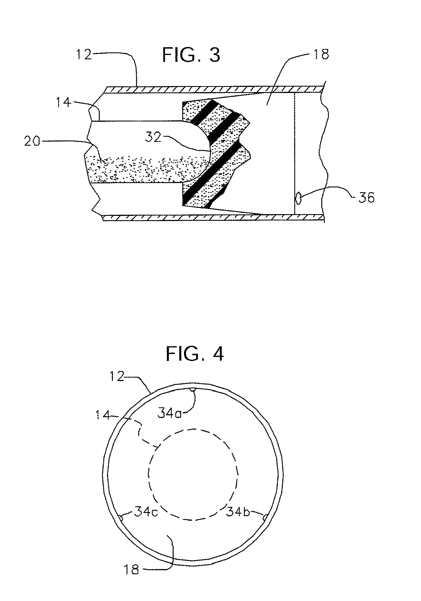
[0119]Centering of ampoule 14 as depicted in FIG. 2 is accomplished by forming concavity 32 in the inboard end of each filter 16, 18. FIG. 3 depicts concavity 32 formed in filter 18; the concavity formed in filter 16 has the same construction. As indicated in FIG. 3, the radius of curvature of each concavity is equal and complementary to the radius of curvature of the rounded ends of ampoule 14 so that the ends of said ampoule are perfectly seated within their respective concavities in stable, non-shifting relationship therewith. This structure main...
third embodiment
[0122]However, the concavities do not solve the problem associated with unwanted longitudinal displacement of the filters of the type depicted in FIG. 1. The solution to that problem is embodied in the invention which is also depicted in FIG. 2. At least one radially inwardly projecting protrusion 34 is formed in deformable housing 12 in outboard relation to filter 16 and at least one radially inwardly projecting protrusion 36 is formed in deformable housing 12 in outboard relation to filter 18. Each protrusion 34, 36 provides a detent means that prevents sliding of said filters away from ampoule 14. Thus, ampoule 14 prevents travel of the filters in an inboard direction and detents 34, 36 prevent travel of the filters in an outboard direction.
[0123]As depicted in FIG. 4, multiple protrusions may be formed in said deformable housing 12. In the example of FIG. 4, three protrusions 34a, 34b, and 34c are disposed in equidistantly and circumferentially spaced apart relation to one anoth...
PUM
| Property | Measurement | Unit |
|---|---|---|
| ineffective time | aaaaa | aaaaa |
| time | aaaaa | aaaaa |
| compressive forces | aaaaa | aaaaa |
Abstract
Description
Claims
Application Information
 - R&D
- Intellectual Property
- Life Sciences
- Materials
- Tech Scout
- Unparalleled Data Quality
- Higher Quality Content
- 60% Fewer Hallucinations
Browse by: Latest US Patents, China's latest patents, Technical Efficacy Thesaurus, Application Domain, Technology Topic, Popular Technical Reports.
© 2025 PatSnap. All rights reserved.Legal|Privacy policy|Modern Slavery Act Transparency Statement|Sitemap|About US| Contact US: help@patsnap.com


