Electrical device

a technology of electrical devices and electrical components, applied in the direction of electrical apparatus casings/cabinets/drawers, hermetically sealed casings, semiconductor/solid-state device details, etc., can solve the problems of high pressure and difficulty in liquid impinging on electrical devices, and achieve the effect of easy manufacturing

Inactive Publication Date: 2010-11-23
ROBERT BOSCH GMBH
View PDF19 Cites 11 Cited by
  • Summary
  • Abstract
  • Description
  • Claims
  • Application Information

AI Technical Summary

Benefits of technology

[0003]The electrical device according to the present invention has the advantage that the design of the impact protection element as a part connected in one piece to the housing part results overall in an electrical device having a pressure compensation element which on the one hand is very effective and on the other hand is very easy to manufacture.
[0004]According to a further embodiment of the present invention, the impact protection element is situated in a recess and extends or rises above a base of the recess. As a result of these measures it is very difficult for the liquid impinging on the electrical device, for example during high-pressure cleaning using a compact high-speed liquid jet, to, on the one hand, deflect this liquid jet onto the impact protection element, and on the other hand, to exert high pressure on the surfaces at that location. These measures on the one hand avoid liquid even reaching the region of the pressure compensation element, and on the other hand avoid liquid striking the surfaces at a high momentum. As a result of these measures, very little liquid reaches a diaphragm at all. If the impact protection element is fastened to the base of the above-mentioned recess via individual supports, it is possible to provide openings which enable air exchange with the interior of the housing for the electrical device. When the outer sides of the supports form an enveloping surface in the shape of a truncated cone, this results, on the one hand, in the above-mentioned surface which is hardly exposable to a direct liquid jet, and on the other hand this design allows this contour of the pressure compensation element to be easily demolded from an injection mold. This injection mold is necessary for manufacturing the housing part having the contour of the pressure compensation element.
[0005]As the result of providing openings between the supports which are oriented essentially perpendicular to the outwardly facing surface of the impact protection element, the openings are hardly impacted directly by the above-mentioned liquid jet, so that there is little or no impingement by the liquid jet on the diaphragm located therebeneath. This allows the diaphragm to reliably remain fixed in place; i.e., the diaphragm is not detachable under liquid pressure. If the preferably circular diaphragm is fastened to a back side of the base facing the interior of the housing, preferably by use of an integral jointing process, on the one hand the diaphragm is particularly well protected from the outside and on the other hand a particularly large annular surface on the back side of the base is obtained which is used to fasten the diaphragm. Thus, the diaphragm surface is also independent of the surface area of the openings between the surroundings of the electrical device and the diaphragm.

Problems solved by technology

As a result of these measures it is very difficult for the liquid impinging on the electrical device, for example during high-pressure cleaning using a compact high-speed liquid jet, to, on the one hand, deflect this liquid jet onto the impact protection element, and on the other hand, to exert high pressure on the surfaces at that location.

Method used


Image

  • Electrical device
  • Electrical device
  • Electrical device

Examples


Embodiment Construction

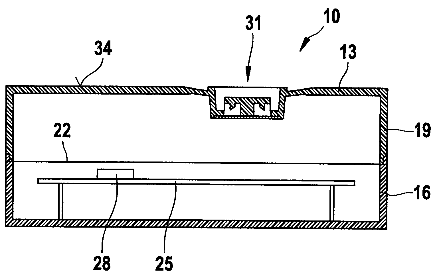
[0018]FIG. 1 shows a cross section of an electrical device 10. Electrical device 10 has a housing 13 composed of a lower housing part 16 and an upper housing part 19. Both housing parts 16 and 19 together form housing 13 having joint 22. In housing 13 itself a printed circuit board 25 is provided, to which the moisture-sensitive electrical modules, for example electrical module 28, are fastened. Upper housing part 19 has a pressure compensation element 31 which allows gas exchange through a surface 34 of housing part 19. This gas exchange is necessary so that housing 13 is not exposed to excessive mechanical stresses at various external temperatures. The aim is to avoid leaks from occurring in the housing or that external or internal air pressure even destroys the housing.

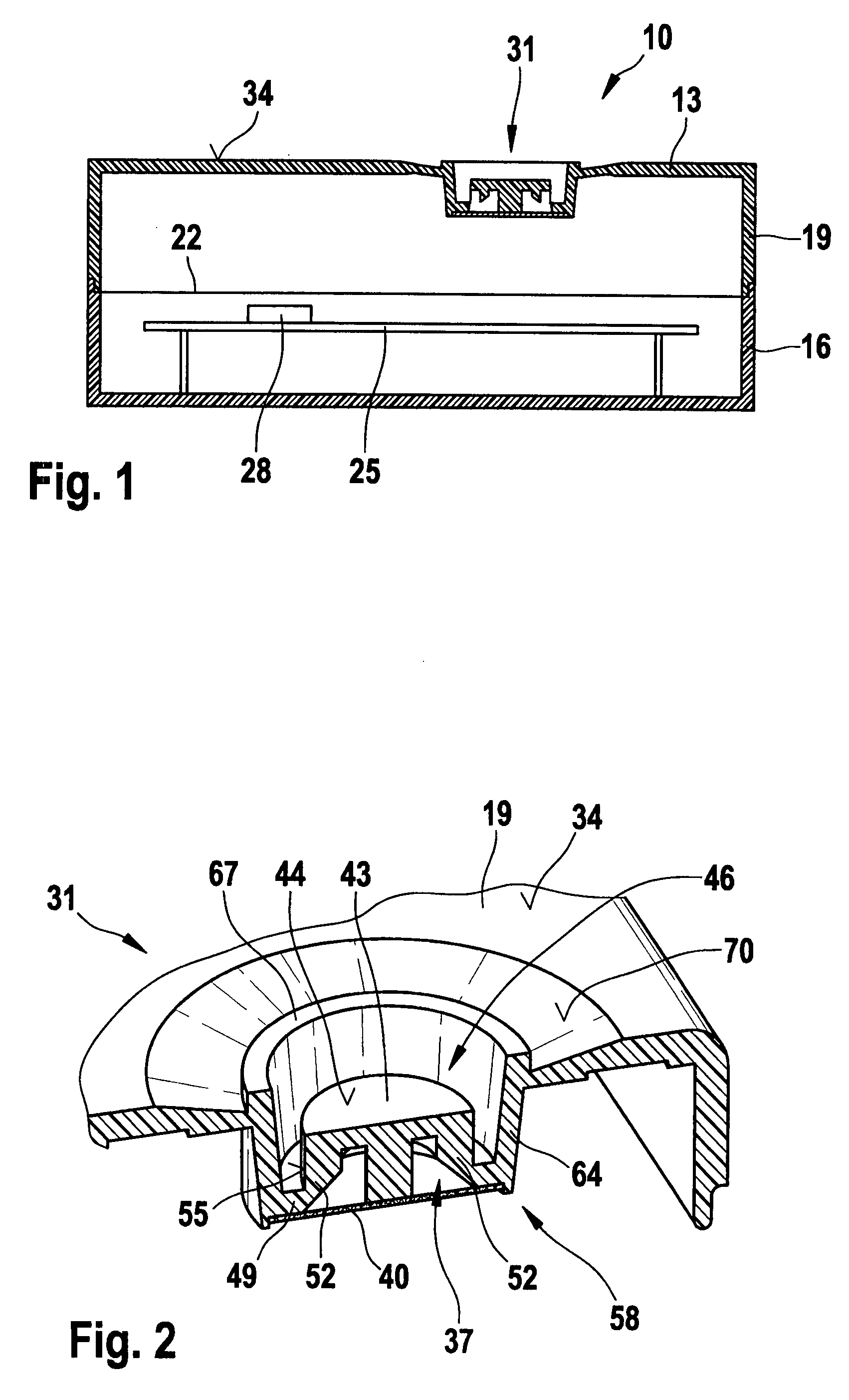
[0019]FIG. 2 shows a three-dimensional view of a section of pressure compensation element 31 mentioned above. In this case the line of vision is directed on outer surface 34 of housing 13. On its upper surface 34 h...


PUM


Abstract

An electrical device having a housing and moisture-sensitive electrical structural units situated in the housing, having a pressure compensation element situated in a housing part, which avoids, preferably prevents, the ingress of moisture, the pressure compensation element including a diaphragm which is permeable to gas, having an impact protection element situated in front of the diaphragm, which at least avoids spraying a liquid directly onto the diaphragm, wherein the impact protection element is in one piece part of the housing part.

Description

FIELD OF THE INVENTION[0001]The present invention relates to an electrical device having a pressure compensation element.BACKGROUND INFORMATION[0002]An electrical device having a pressure compensation element is described in German Patent Application No. DE 38 17 227, in which the pressure compensation element is inserted into an opening in a housing. A disadvantage of this design is that on the one hand the pressure compensation element is composed of numerous individual parts, and on the other hand an additional joining process is necessary for fastening the pressure compensation element in the housing.SUMMARY OF THE INVENTION[0003]The electrical device according to the present invention has the advantage that the design of the impact protection element as a part connected in one piece to the housing part results overall in an electrical device having a pressure compensation element which on the one hand is very effective and on the other hand is very easy to manufacture.[0004]Acc...

Claims


Application Information

Patent Timeline
Patent Type & Authority Patents(United States)
IPC IPC(8): H05K5/06
CPCH05K5/068H05K5/0215H05K5/0213
Inventor ZADACH, PETERKUHN, JOCHEN
Owner ROBERT BOSCH GMBH
Why Eureka
Try Eureka