Apparatus and system for transmitting power wirelessly

a wireless transmission and wireless technology, applied in the structure of radiating elements, waveguide devices, resonance antennas, etc., can solve the problems of difficult power transmission, inability to achieve power transmission, and inability to wirelessly provide power to a variety of mobile devices or industrial robots

Active Publication Date: 2010-11-30
SAMSUNG ELECTRONICS CO LTD +1
View PDF15 Cites 204 Cited by
  • Summary
  • Abstract
  • Description
  • Claims
  • Application Information

AI Technical Summary

Benefits of technology

[0014]The power transmitting and receiving efficiency may increase as resonant frequencies of each dielectric resonator of the power transmitting apparatus and the power receiving apparatus become closer to each other.

Problems solved by technology

Recently, wireless power transmission technology that can wirelessly provide power to a variety of mobile devices or industrial robots has become an issue.
However, the inductive coupling enables power transfer within a very limited range, and power transfer is not possible if the coils are not accurately aligned with each other.
However, in this case, power is radiated in all directions, and thus efficient power transmission is hard to be achieved.

Method used


Image

  • Apparatus and system for transmitting power wirelessly
  • Apparatus and system for transmitting power wirelessly
  • Apparatus and system for transmitting power wirelessly

Examples


Embodiment Construction

[0022]The invention is described more fully hereinafter with reference to the accompanying drawings, in which exemplary embodiments of the invention are shown. Hereinafter, in describing the present invention, detailed descriptions of relevant functions or structures well-known to those skilled in the art will be omitted when it is considered that the descriptions obscure the point of the present invention. The terms used herein are defined in consideration of the functions of elements in the present invention, and may be varied according to the intentions or the customs of a user and an operator.

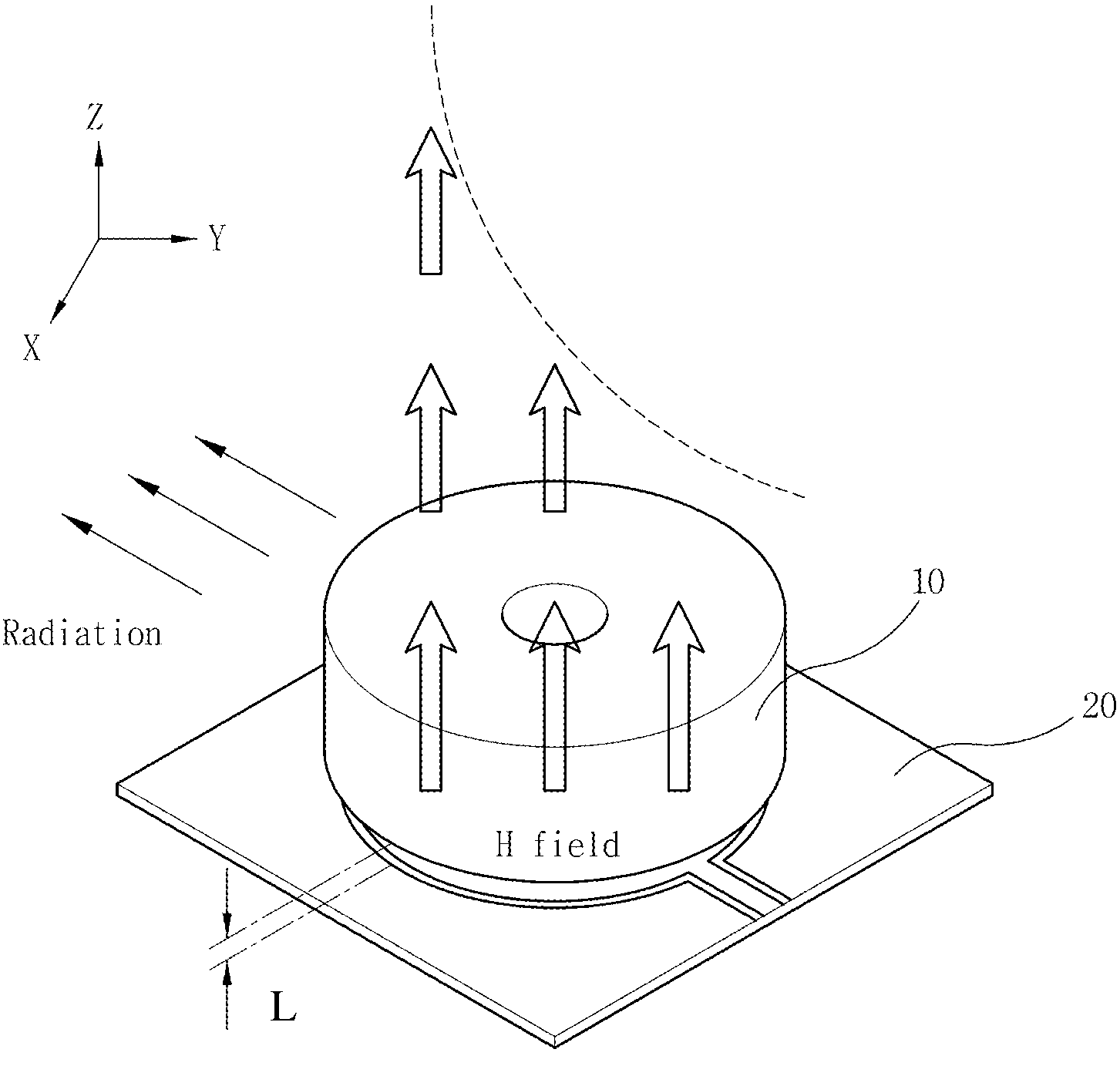
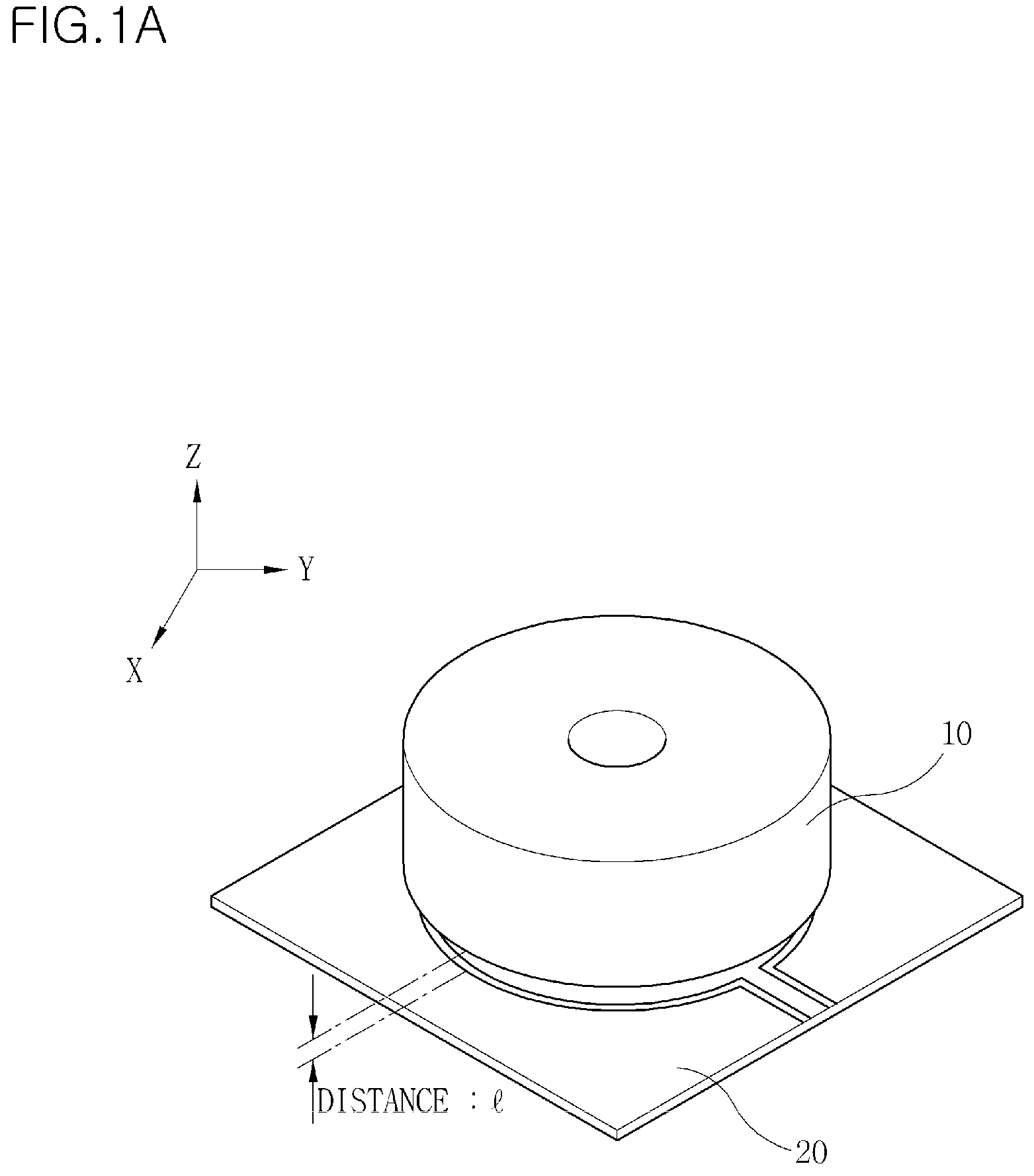
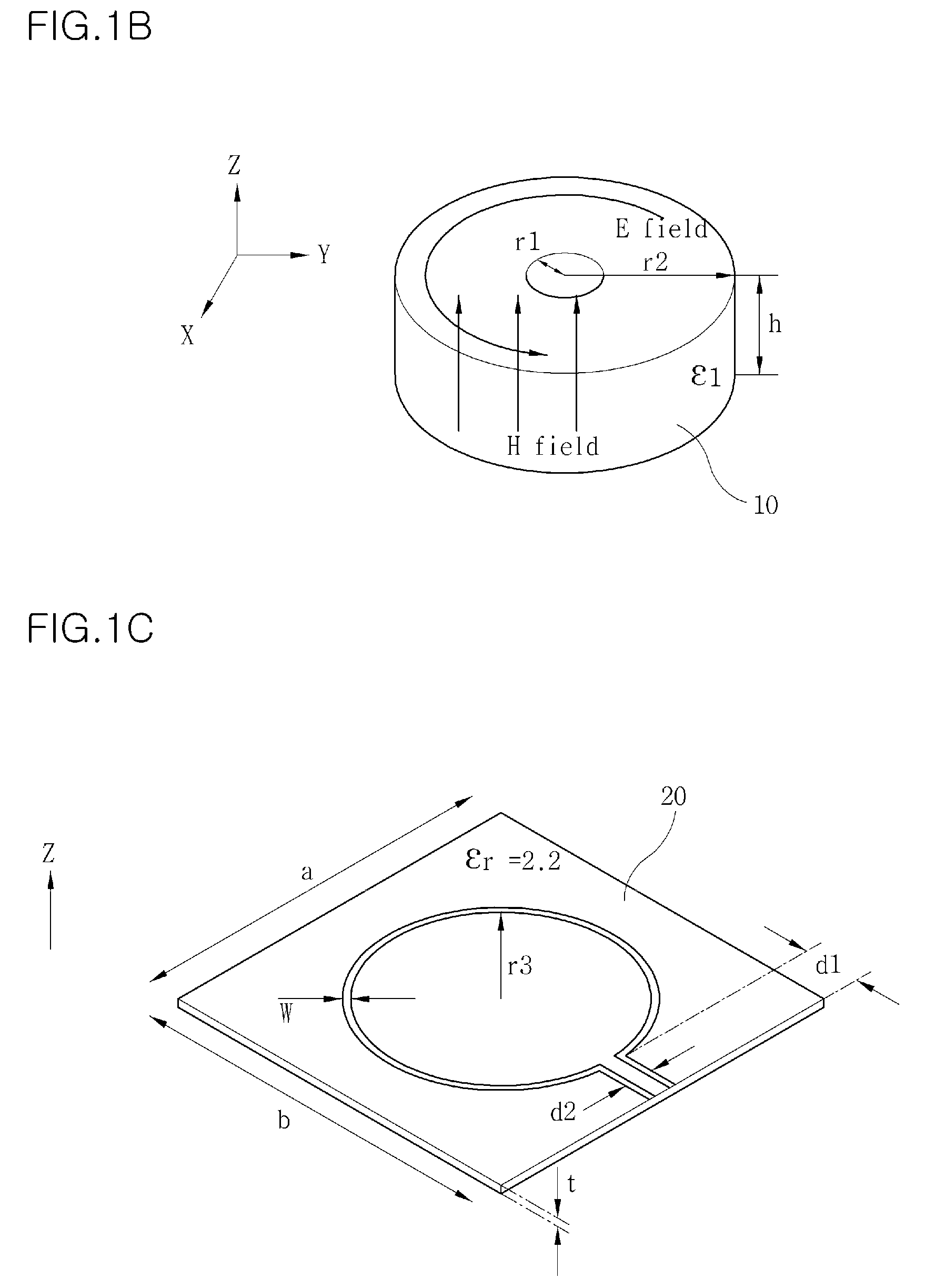
[0023]FIGS. 1A to 1C illustrate structures of a wireless power transmitting apparatus according to an embodiment of the present invention.

[0024]A short-distance wireless power transmitting apparatus employed by the present invention is a dielectric resonator antenna. FIG. 1A shows the entire dielectric resonator antenna, FIG. 1B shows a structure of a dielectric resonator 10 and magnetic an...


PUM


Abstract

An apparatus for transmitting power wirelessly is provided. The apparatus comprises: a dielectric resonator which generates evanescent waves in a predetermined direction in order to transmit power; and a loop antenna which is coupled to a surface of the dielectric resonator and supplies power to the dielectric resonator. The dielectric resonator transmits power by means of evanescent waves generated in directions perpendicular to top and bottom surfaces of the dielectric resonator and by radiation in directions parallel to the top and bottom surfaces of the dielectric resonator. Accordingly, efficient power transmission over short and long distance ranges is possible.

Description

CROSS-REFERENCE TO RELATED APPLICATIONS[0001]This application claims priority from Korean Patent Application Nos. 10-2007-00116901 and 10-2007-0138983, respectively, filed on Nov. 15, 2007 and Dec. 27, 2007, the disclosures of which are incorporated herein in its entirety by reference.BACKGROUND OF THE INVENTION[0002]1. Field of the Invention[0003]The present invention relates to a power transmitting apparatus, and more particularly, to an apparatus and a system for transmitting and receiving power wirelessly.[0004]2. Description of the Related Art[0005]Recently, wireless power transmission technology that can wirelessly provide power to a variety of mobile devices or industrial robots has become an issue. Inductive coupling and radiative coupling are typically used for wireless power transmission.[0006]In inductive coupling, a number of coils are used such that a magnetic field is strongly induced in one direction, and when coils which resonate at a similar frequency become very cl...

Claims


Application Information

Patent Timeline
Patent Type & Authority Patents(United States)
IPC IPC(8): H01P7/10
CPCH01Q7/00H01Q9/0485
Inventor LEE, DONG-HYUNPARK, KYUNG-HOPARK, WEE-SANGKIM, JAE-HEEMUHN, SUNG-JINWOO, DAE-WOONG
Owner SAMSUNG ELECTRONICS CO LTD
Why Eureka
Try Eureka