
Food processing device

a technology for processing devices and food, which is applied in the field of food processing devices, can solve problems such as incomplete separation of paste, and achieve the effect of uniform paste flow rate and enhanced cutting action of knives

Active Publication Date: 2010-12-07
MACHINEFAB GEURTSEN DEVENTER
View PDF15 Cites 3 Cited by
  • Summary
  • Abstract
  • Description
  • Claims
  • Application Information

AI Technical Summary

Benefits of technology

[0008]According to a further advantage of the invention it has been found that by use of a pair of knives rather than a single knife, the item may be formed with a desired longitudinal profile. Furthermore, the use of a pair of knives allows the knives to completely overlap ensuring complete severance of the paste. Known iris configurations cannot overlap at the central point and can lead to incomplete severance of the paste, especially in the case that it has a stringy consistency.
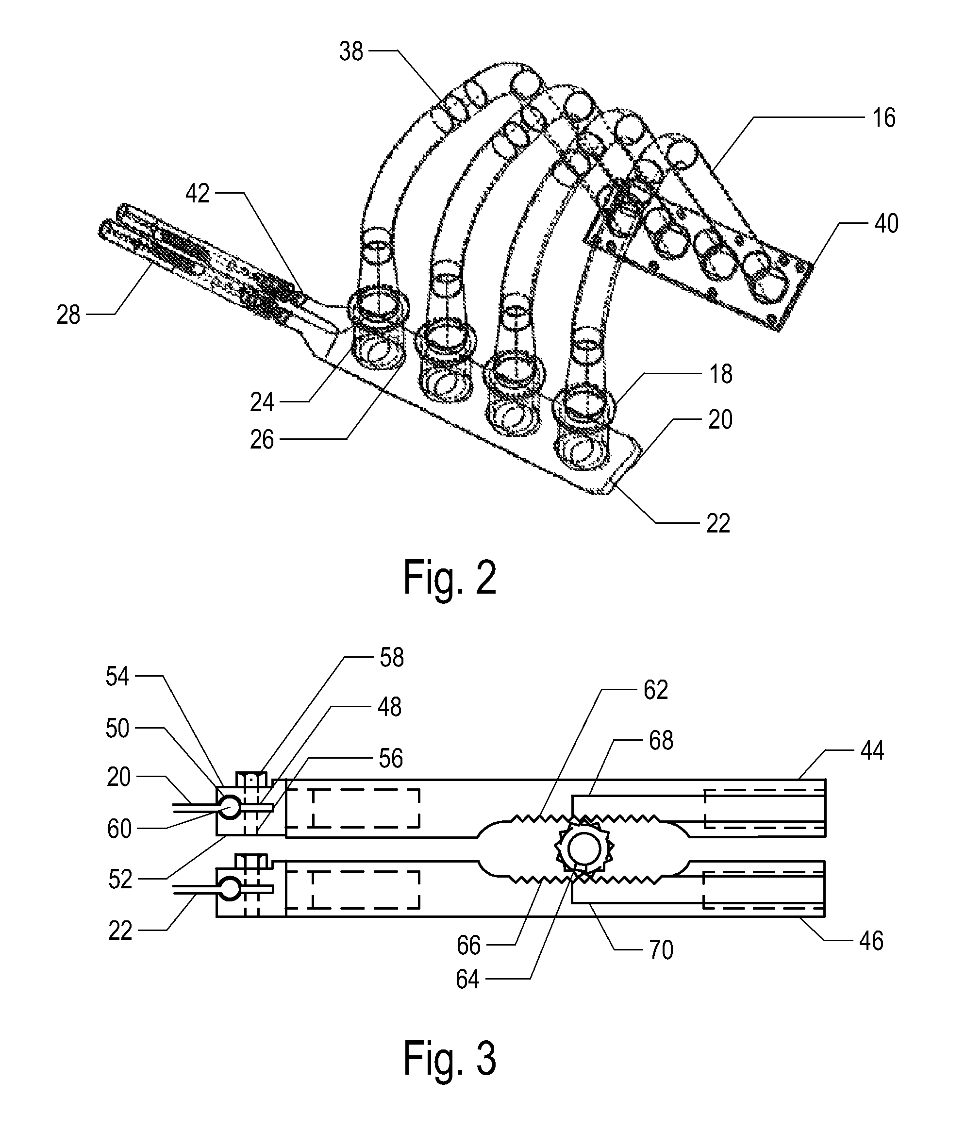
[0009]According to a preferred embodiment of the invention each knife comprises a generally flat plate aligned generally perpendicular to an axis of the nozzle and provided with an aperture for alignment with the nozzle. The knives may be mounted for transverse reciprocal movement with respect to one another from an open position in which the apertures are generally coaxial with the nozzle, to a closed position in which the apertures are out of alignment and each partially closes the nozzle. The knives may each move from a closed position to an open position and then return to the original closed position. The knives may also be double-acting and move from a closed position to an open position and then continue to a new closed position. Alternatively, the motion may be from an open position through a closed position and on to a second open position.
[0010]Particularly for use with paste that may contain inclusions such as fibres, gristle or bones, the knives may be provided with a cutting edge located on a first side of the aperture. The cutting edge may for instance be asymmetric with respect to the remainder of the aperture whereby on reciprocal movement of the knives, the cutting action of the knives is enhanced. In this way, a slicing motion may be achieved, especially in the last part of the cutting stroke. Preferably, the cutting edge or edges may be sharpened or serrated according to the required performance. For double-acting knives, two cutting edges may be provided.
[0011]According to a particular advantage of the present invention, the device may comprise a plurality of nozzles. By providing each knife with a plurality of apertures corresponding to the plurality of nozzles, a number of items may be formed at each actuation of the knives. The use of individual nozzles allows the paste supply to each nozzle to be controlled, ensuring homogeneity between all the formed items. Control of the paste supply may be achieved using known flow divider devices that ensure equal division of a paste supply between a number of outlets. In the present context by “flow divider” is meant an device that actively ensures a correct division between the different flow paths as opposed to a manifold that is susceptible to variation. The flow divider may be driven or non-driven. In the case of a plurality of nozzles, all nozzles may open and close together. It may however be preferable to arrange the nozzles and knives in pairs whereby one nozzle in a pair opens as the other one closes. Such an arrangement can be advantageous in combination with a uniform paste flow rate to the nozzle pair.
[0012]For a multiple outlet device, the axes of the nozzles are preferably generally parallel to one another and aligned with a direction of movement of the knives. Other configurations may also be used while still adhering to the principle of overlapping knives according to the invention. Thus, the nozzles may be aligned in a first direction e.g. from left to right, while the movement of the knives may be perpendicular to this direction e.g. up and down. In an alternative more compact embodiment, the nozzles may be arranged in a circular configuration and the knives may be embodied as a pair of disks each having apertures aligned with the nozzles. The disks may reciprocate as in earlier embodiments but may also continuously counter-rotate.
[0013]It has also been found advantageous to provide a resilient mounting for the knives. According to this feature of the invention, the knives may be mounted to move away from the nozzle should excess pressure build up in the paste supply nozzle, whereby paste can escape laterally from between the nozzle and the knives. The mounting may be provided by a spring arrangement which biases the knives against the nozzle with a given tension, that may be adjustable.

Problems solved by technology

Known iris configurations cannot overlap at the central point and can lead to incomplete severance of the paste, especially in the case that it has a stringy consistency.

Method used


Image

  • Food processing device
  • Food processing device
  • Food processing device

Examples


Embodiment Construction

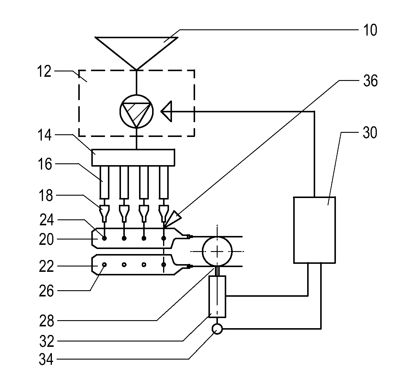
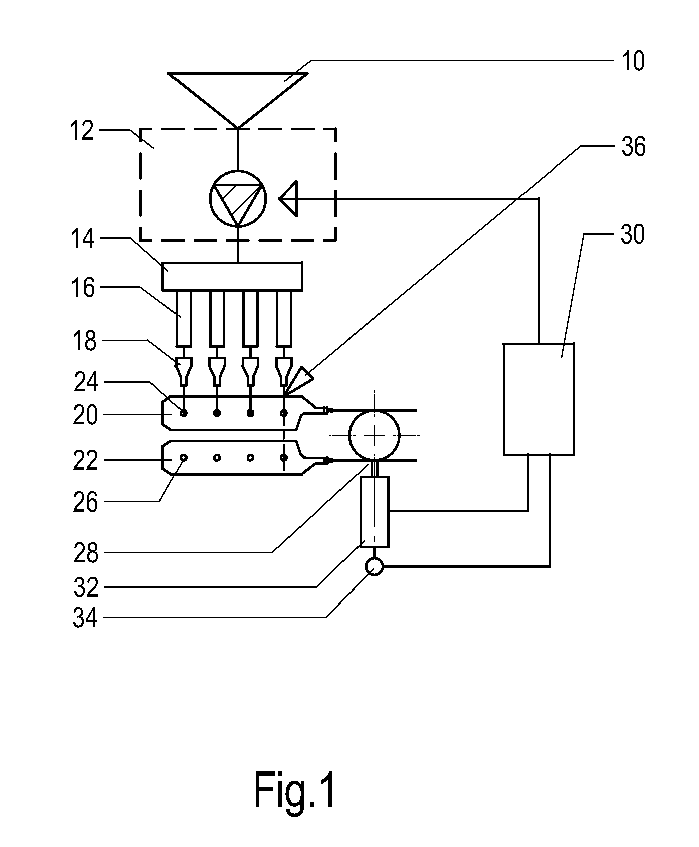
[0027]FIG. 1 shows a schematic view of the principle components of a meatball forming device 1 according to an aspect of the present invention. The device1 comprises a paste reservoir 10, a feed pump 12 and a flow divider 14. The feed pump 12 may be any conventional pump suitable for providing a constant stream of meat paste from the reservoir 10 to the flow divider 14. The flow divider 14 is preferably a rotary flow divider such as the non-driven vane type device known from PCT publication No WO98 / 22206, the contents of which are hereby incorporated by reference in their entirety. Other forms of distribution may also be used to divide the flow of paste from the pump 12 to a plurality of supply lines 16. The flow divider 14 is provided with outlets to four supply lines 16 all of which receive a substantially equal supply of paste as a result of the operation of the flow divider 14. Each of the outlets 16 is connected to a nozzle 18. A pair of knives 20, 22 is located ahead of the no...


PUM


Abstract

A food processing device comprises a paste reservoir, a feed pump and a flow divider. The flow divider is provided with outlets to four supply lines all of which receive a substantially equal supply of paste as a result of the operation of the flow divider. Each of the outlets is connected to a nozzle. A pair of knives is located ahead of the nozzles, each being provided with four apertures. The knives are provided with an actuating mechanism and a controller. Controller registers and controls operation of the meatball forming device and is electrically connected to the feed pump, to a servomotor and to a shaft encoder.

Description

BACKGROUND OF THE INVENTION[0001]1. Field of the Invention[0002]The present invention relates to a device for food processing, in particular for the processing of pasty foods for the purpose of forming shaped items such as balls, sausages or the like. The invention also covers methods of forming individually shaped items of such pasty food.[0003]2. Description of the Related Art[0004]It is known in the prior art to produce meatballs from a continuous supply of meat paste. The meat paste may be supplied by a conventional dosing pump, which feeds the product to one or more dispensing heads. At the head, a valve or knife periodically cuts the flow of paste into individual lengths, which may then drop into hot water for cooking or may be subjected to any other further treatment as required. A device of this type is known which uses an iris type diaphragm valve to cut the paste. The construction of the valve is complex requiring a large number of moving parts. For use in the food industr...

Claims


Application Information

Patent Timeline
Patent Type & Authority Patents(United States)
IPC IPC(8): A47J37/12
CPCA22C11/006A23P1/12A23P30/20
Inventor DIETRICH, WARDO JACOB HENDRIK
Owner MACHINEFAB GEURTSEN DEVENTER
Learn More