Soldering apparatus and soldering method

Inactive Publication Date: 2010-12-07
CHENG UEI PRECISION IND CO LTD
View PDF13 Cites 41 Cited by
  • Summary
  • Abstract
  • Description
  • Claims
  • Application Information

AI Technical Summary

Benefits of technology

[0015]As described above, the soldering apparatus provides the daubing device for dispensing the solder paste to the soldering area of the electronic component where the conducting wires are located, and the soldering device for heating the solder paste to make the insulators of the conducting wires shrink so as to expose the core wires. The solder paste cool down and connect the core wires to the soldering area of the electronic component. S

Problems solved by technology

However, the efficiency of the manual soldering is lower.
The solder wires, used as th

Method used


Image

  • Soldering apparatus and soldering method
  • Soldering apparatus and soldering method
  • Soldering apparatus and soldering method

Examples


Embodiment Construction

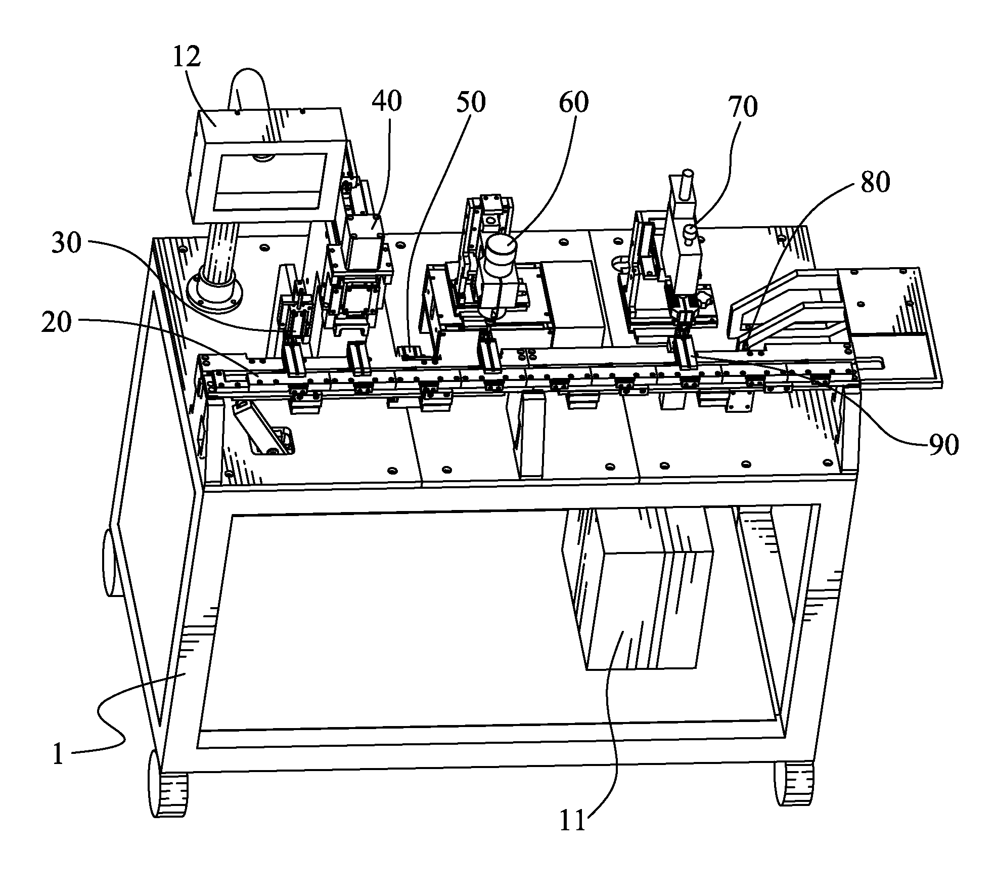
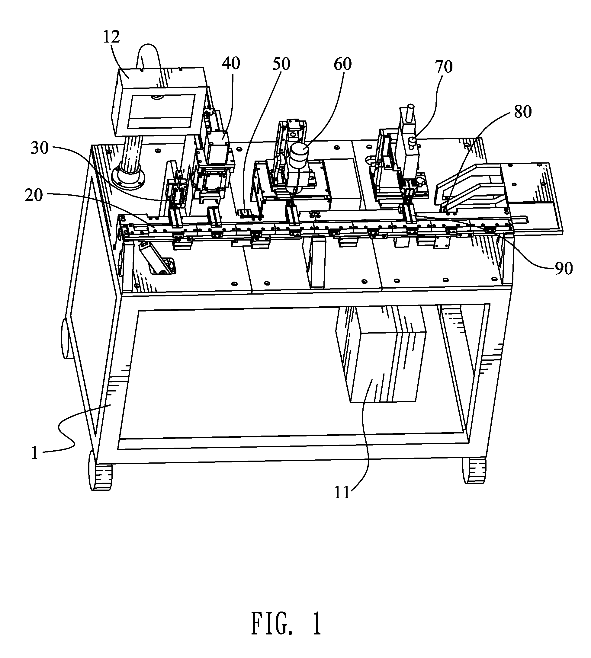
[0031]Referring to the drawings in greater detail, and first to FIG. 1 and FIG. 5, the embodiment of the invention is shown in a soldering apparatus. The soldering apparatus has a supporting platform 1, a processing system, and a convey mechanism 2 mounted on the supporting platform 1. The processing system includes a controller 11, an operating panel 12 connected with the controller 11, a plurality of sensors (not shown). The convey mechanism 2 has a convey element 21 and a pushing element 22. A separating device 30, a cutting device 40, an assembling device 50, a daubing device 60, a soldering device 70 and a discharging device 80 are fixed on the supporting platform 1 and arranged at a rear side of the convey element 21 in turn. A plurality of fixtures 90 are slidably mounted to the convey element 21. The sensors are mounted to a bottom of the convey element 21, corresponding to the separating device 30, the cutting device 40, the assembling device 50, the daubing device 60, the ...


PUM

PropertyMeasurementUnit
Areaaaaaaaaaaa
Distanceaaaaaaaaaa

Abstract

A soldering apparatus has a fixture receiving an electronic component and a conducting wire, with a free end of the conducting wire superimposed on the soldering area of the electronic component, a convey mechanism capable of transmitting the fixture downstream, a daubing device, and a soldering device. The daubing device has a level movable element capable of moving along a convey direction of the convey mechanism, and a vertical movable element mounted on the level movable element and capable of moving along an upward and downward direction. A carrier mounted to the vertical movable element has a solder paste can for loading the solder paste, and an output portion for dispensing the solder paste to the soldering area. The soldering device has a soldering head heating the solder paste for shrinking the insulator, with the core wire exposing and connected to the soldering area by the cool solder paste.

Description

BACKGROUND OF THE INVENTION[0001]1. Field of the Invention[0002]The present invention relates to a soldering apparatus, and particularly to a soldering apparatus adapted for soldering a conducting wire to an electronic component and a soldering method for the same.[0003]2. The Related Art[0004]The connecting cable, such as high density multichip interconnect (HDMI) cable, universal serial bus (USB) cable and the like, is widely used to electrically connect with two electronic devices for transmitting electrical signals. The connecting cable generally has two electronic components, and a cable having a plurality of conducting wires soldered to corresponding soldering areas of the two electronic components. As the soldering operation for manufacturing the connecting cables, at present, is executed in manual way, the solder wires are usually used as the soldering material for convenient operation. In the process of manually soldering the conducting wires to the electronic components, f...

Claims


Application Information

Patent Timeline
IPC IPC(8): B23K37/00B23K31/02
CPCB23K1/0016B23K3/0638B23K2201/38B23K2101/38
Inventor CHEN, LU YANGZHENG, YONGCHENG, RIGUANGZHANG, HUA
Owner CHENG UEI PRECISION IND CO LTD
Why Eureka
Try Eureka