Transparent antenna for display, translucent member for display with an antenna and housing component with an antenna

a technology of transparent antenna and translucent member, which is applied in the direction of resonant antenna, substantially flat resonant elements, shielding material radiating elements, etc., can solve the problems of poor appearance and design, bulky rod antenna, inconvenient carrying, etc., and achieve good transmission and reception, improve receiver sensitivity, and improve the effect of sensitivity

Inactive Publication Date: 2010-12-07
NISSHA PRINTING COMPANY
View PDF27 Cites 50 Cited by
  • Summary
  • Abstract
  • Description
  • Claims
  • Application Information

AI Technical Summary

Benefits of technology

[0013]By a transparent antenna for a display of the present invention, since an electrically conductive part constituting the antenna pattern is formed into a mesh structure having a multitude of apertures, and outlines of each mesh are composed of extra fine bands, there is an advantage that the antenna pattern is recognized only as a slight variation of shading when looking at the display screen through the transparent antenna for a display.
[0049]In accordance with the housing component with an antenna, an electrically conductive part of the antenna pattern is formed into a mesh structure having a number of apertures, and since outlines of each mesh are composed of extra fine bands, when looking at an opaque decorative section and an illumination-decoration section where a decorative effect can be obtained by illumination, the antenna pattern is recognized only as a slight variation of shading, so that a design provided on the housing is not damaged by the attached antenna. Further, a front surface of a relatively large display can be used for a space for mounting the antenna so that receiver sensitivity can be improved and good transmission and reception are made possible. The light transmittance is preferably 80% or more.

Problems solved by technology

However, the loop antenna and the rod antenna are bulky and are not good in terms of appearance and design, and are inconvenient in carrying.
With respect to an antenna for mobile devices, receiver sensitivity is not always satisfactory since the antenna is stored inside a limited space.

Method used


Image

  • Transparent antenna for display, translucent member for display with an antenna and housing component with an antenna
  • Transparent antenna for display, translucent member for display with an antenna and housing component with an antenna
  • Transparent antenna for display, translucent member for display with an antenna and housing component with an antenna

Examples


first embodiment

a-1. First Embodiment of the Transparent Antenna for a Display

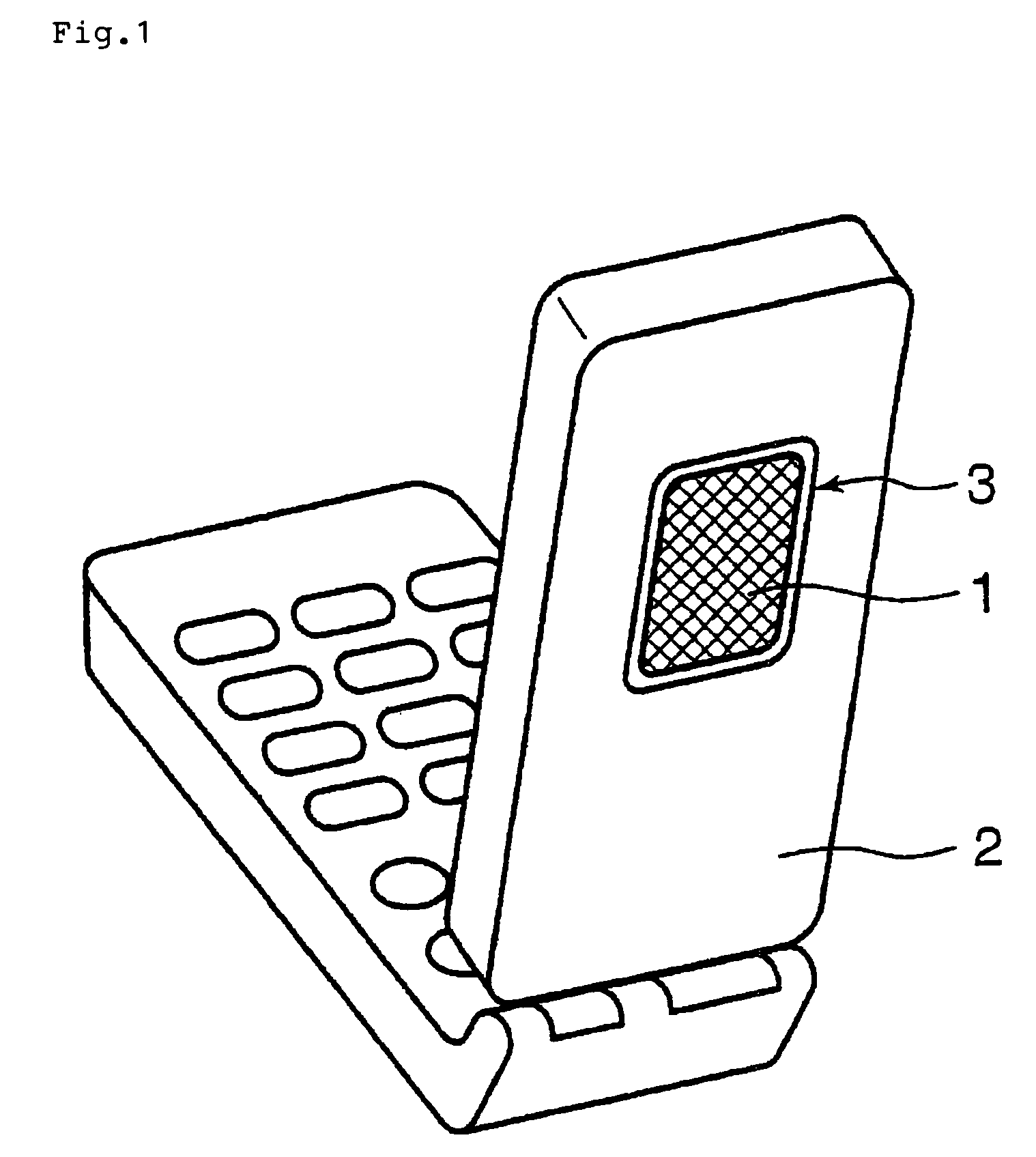
[0094]FIG. 1 is a schematic diagram showing a state in which the transparent antenna for a display (hereinafter abbreviated as transparent antenna) 1 according to a first embodiment of the present invention is attached to a display screen 3 of a cellular phone handset 2.

[0095]The cellular phone handset 2 is a two-folded type handset equipped with a display screen (sub window) 3 on an outer surface when it is folded. A transparent antenna 1 is attached on an entire display area of the display screen 3.

[0096]An electrode for power supply of the transparent antenna 1 is connected to a transmission and reception section in the cellular phone handset 2 via an input-output terminal disposed on an outer frame of the display screen 3.

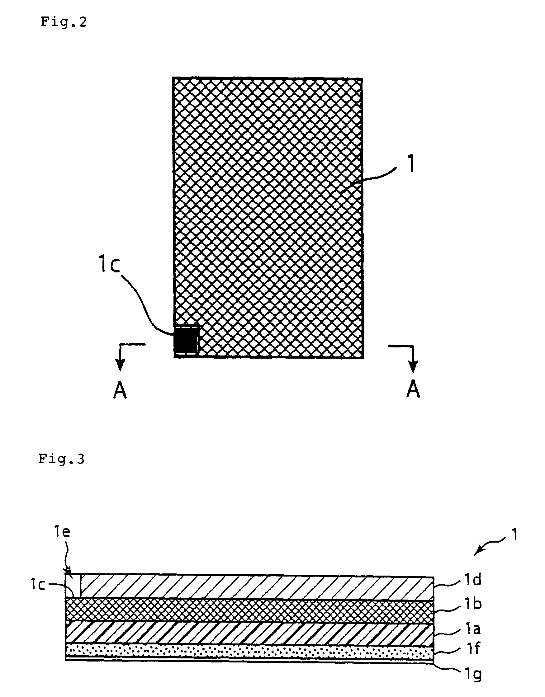
[0097]In FIG. 2, the transparent antenna 1 having an antenna pattern by an electrically conductive part 1b is formed on a transparent plastic sheet 1a as a transparent substrate having an electrical ...

example 1

[0143]Hereinafter, the present invention will be described in more detail with reference to Examples, but the present invention is not restricted by the following Examples and can be suitably modified within the scope described above or below and such modifications are also included in the technical scope of the present invention.

[0144]On a transparent polyethylene terephthalate film (transparent substrate 1a) with a thickness of 100 μm, a transparent resin layer containing a plating catalyst was formed to be subjected to electroless copper nickel plating, followed by electrolytic copper plating, thereby forming a metal thin film.

[0145]Next, both surfaces of the metal thin film were subjected to chemical conversion treatment(low reflection treatment). Then, an aperture was formed by photo-etching method on the metal thin film (to be an electrically conductive thin film of the mesh structure) to give an antenna pattern.

[0146]The electrically conductive part 1b of this antenna pattern...

example 2

[0153]A copper foil with a thickness of 12 μm having both surfaces with lowered reflectance by chemical conversion treatment was bonded on a transparent polycarbonate film (transparent substrate 1a) having a thickness of 100 μm using a transparent adhesive, and subsequently an antenna pattern of a resist film was printed; after a copper foil except for a resist-covered section was subjected to etching using an etchant, the resist film was removed, thereby forming the antenna pattern. The antenna pattern has an electrically conductive part 1b in which a shape of a mesh aperture thereof is a regular hexagonal lattice pattern, 500 μm on a side, and a line width of a extra fine band 1k (refer to FIG. 5) was 25 μm.

[0154]Then, along the antenna pattern thus prepared, the outside thereof was cut to give a transparent antenna 1. The transparent antenna 1 was inserted in a metal mold for a sub window protection panel of a cellular phone handset to feed a polycarbonate resin in the metal mold...


PUM


Abstract

A transparent antenna for a display, for example, a portable telephone, the transparent antenna performing good transmission and reception, not bulky, and not impairing design of an apparatus. The transparent antenna for a display has an insulating sheet-like transparent substrate and has a planar antenna pattern formed on the surface of the transparent substrate. An electrically conductive section of the antenna pattern is constructed from an electrically conductive thin film of a mesh structure, outlines of each mesh are constituted from extra fine bands with substantially the same width, and the light transmittance of the section where the antenna pattern is formed is equal to or more than 70%.

Description

BACKGROUND OF THE INVENTION[0001]I. Technical Field[0002]The present invention relates to a transparent antenna for a display, a translucent member for a display with an antenna and a housing component with an antenna composed so as to receive terrestrial broadcasting and satellite broadcasting or to transmit and receive radio which are attached to a display screen of a television monitor, a mobile terminal such as a cellular phone handset or built in a housing of a cellular phone handset as a part thereof.[0003]II. Description of the Related Art[0004]In recent years, various broadcastings such as terrestrial digital broadcasting have been provided, and transmission and reception of wireless LAN and transmission and reception via an external network are becoming common. In such a situation, there is a trend of an increasing demand for a miniaturized antenna.[0005]As an indoor antenna for television, a loop antenna, a rod antenna and the like have been conventionally known, and these...

Claims


Application Information

Patent Timeline
Patent Type & Authority Patents(United States)
IPC IPC(8): H01Q1/36
CPCH01Q1/243H01Q1/40H01Q9/0407H01Q9/16H01Q9/30H01Q1/38
Inventor ISHIBASHI, TATSUOOKUMURA, SHUZOMATSUI, YUKIYAMAOKA, YOSHITAKATAKAGI, TAKAYUKIMUKO, HIROMITSUOMOTE, RYOMEI
Owner NISSHA PRINTING COMPANY
Why Eureka
Try Eureka