Frequency synthesizers for wireless communication systems

a technology of wireless communication system and frequency synthesizer, which is applied in the direction of oscillator generator, pulse automatic control, electrical apparatus, etc., can solve the problems of excessive clock jitter, inability or impracticality to implement, and excessive jitter

Active Publication Date: 2010-12-07
ANALOG DEVICES INC
View PDF15 Cites 17 Cited by
  • Summary
  • Abstract
  • Description
  • Claims
  • Application Information

AI Technical Summary

Problems solved by technology

Wireless systems facilitate communications that would be impossible or impractical to implement with the use of wires.
Although this base station structure has the advantage that it reduces RF losses between antennas and associated transceivers, it presents other network problems that may cause excessive clock jitter.
For example, excessive length of the optical link is often sufficient to induce substantial jitter in the network clock and the subsequent use of clock recovery algorithms may also be the source of excessive jitter.

Method used


Image

  • Frequency synthesizers for wireless communication systems
  • Frequency synthesizers for wireless communication systems
  • Frequency synthesizers for wireless communication systems

Examples


embodiment 20

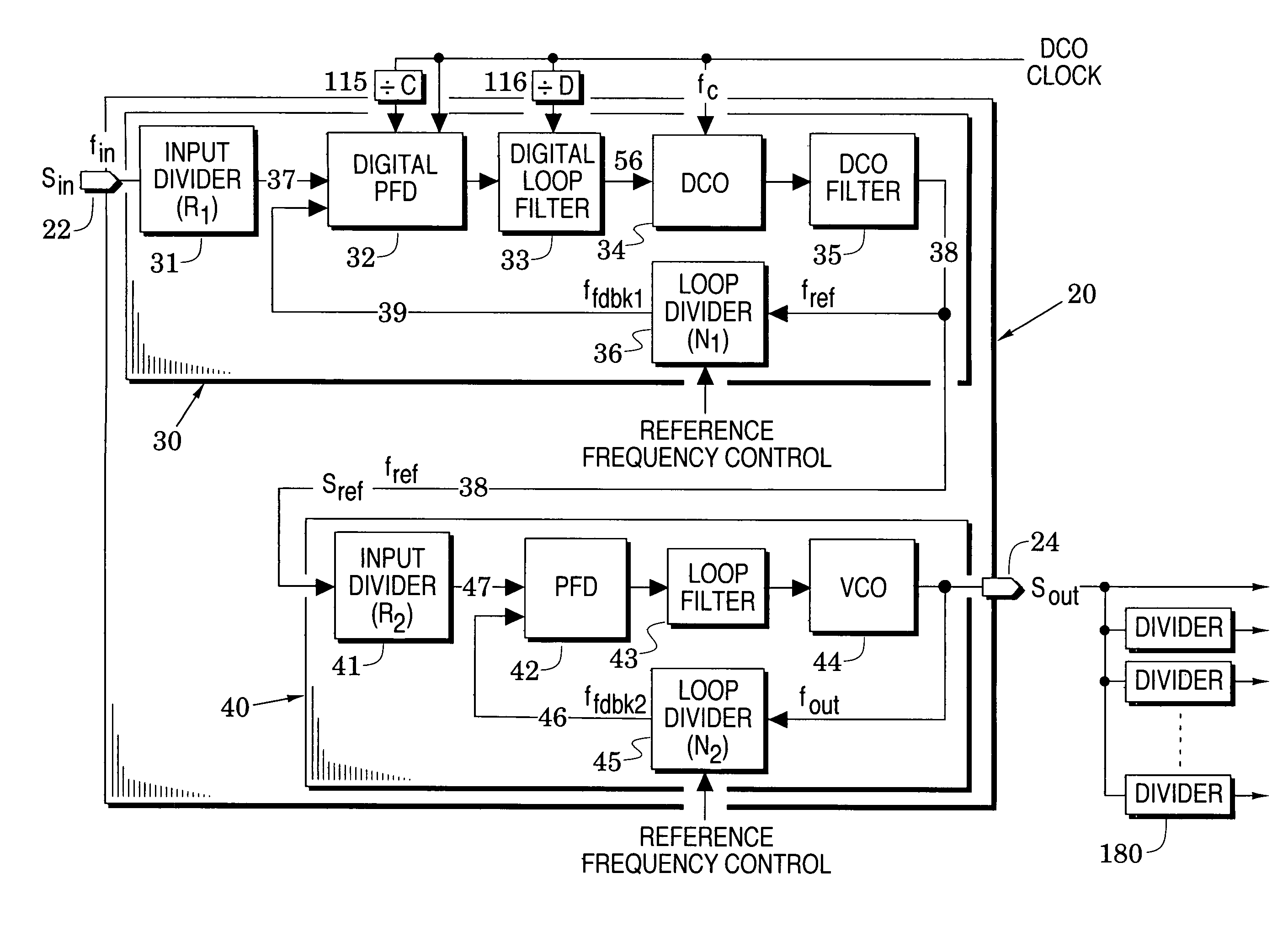
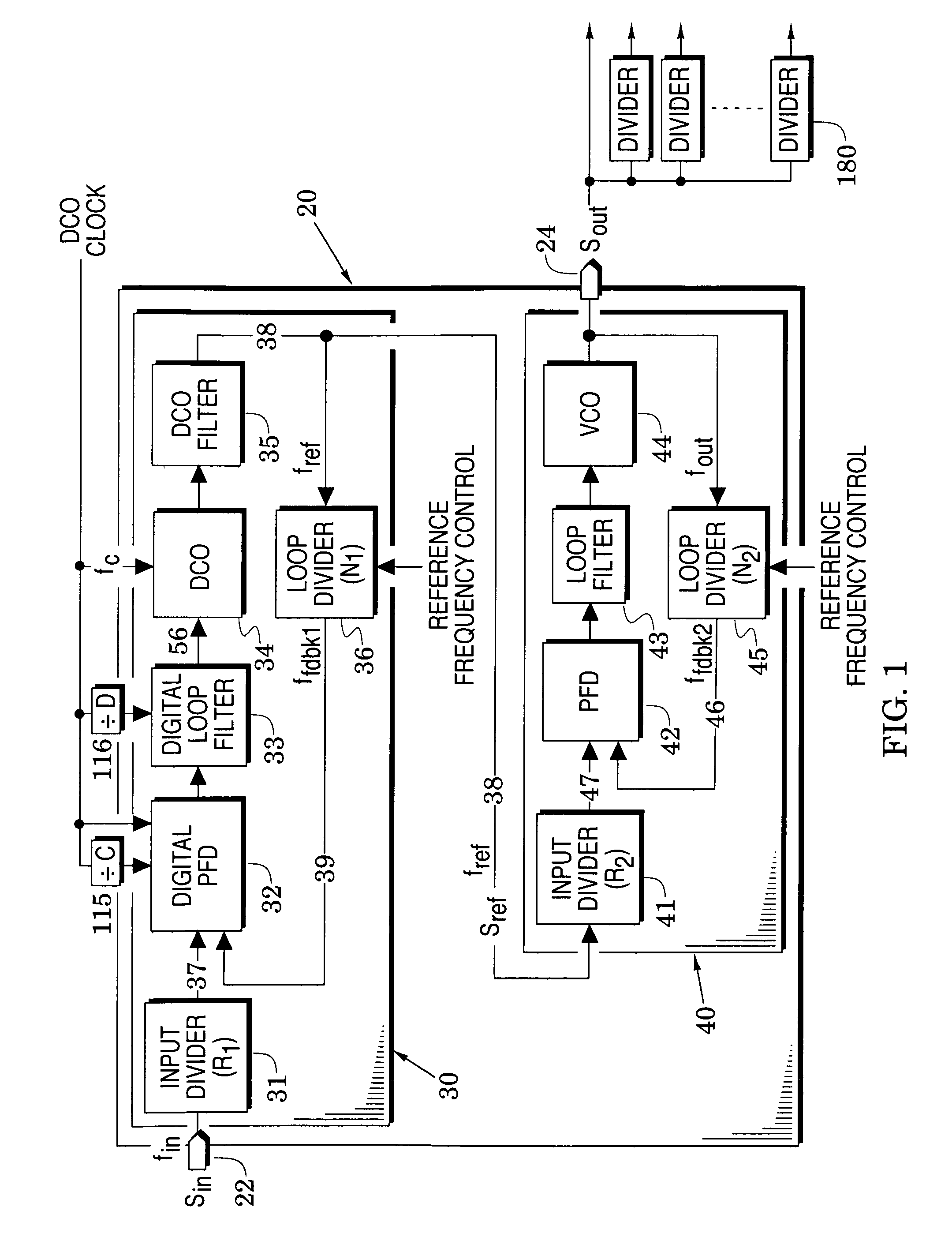
[0018]FIG. 1 illustrates a frequency synthesizer embodiment 20 which processes an input signal Sin at an input port 22 into an output signal Sout at an output port 24. Because of its novel structure, the synthesizer 20 can generate an output signal which provides:

[0019]high frequency resolution,

[0020]substantially reduced spurious signals, and

[0021]low phase noise,

even when the input signal is a network clock which includes significant phase jitter. These advantages are provided with first and second phase-locked loop embodiments 30 and 40 whose details are described below.

[0022]Attention is initially directed to the first phase-locked loop (PLL) 30 which includes a digital phase / frequency detector 32, a digital loop filter 33, a digitally-controlled oscillator (DCO) 34, a DCO filter 35 and a first feedback frequency divider 36. The digital loop filter is coupled between the digital phase / frequency detector and the DCO and the output of the DCO is processed by the DCO filter to form...

embodiment 70

[0038]In embodiments of the second PLL 40 of FIG. 1, the feedforward and feedback frequency dividers 41 and 45 can be formed with simple programmable digital counters. The output frequency fout at the output port 24 may, however, exceed the allowable range of a simple counter. To relieve the frequency demands on the feedback frequency divider 45, FIG. 3 shows a loop divider embodiment 70 formed with a programmable counter 72 that is preceded by a fixed high-frequency prescalar 71 which is configured to operate at higher frequencies.

[0039]The prescalar divides the output frequency by P and the programmable counter divides the frequency of the signal from the prescalar by A. In this embodiment, the output frequency fout is AP times the reference frequency fref (assuming an absence of the feedforward divider 41 in FIG. 1). Although the programmable counter 72 now only has to process a reduced frequency fout / P, the resolution of the second PLL 40 has been reduced to AP in which P is a f...

embodiment 74

[0040]In contrast, FIG. 3 also shows a loop divider embodiment 74 in which the prescalar 71 has been replaced by a dual-modulus prescalar 75 which can be commanded to divide by P or by P+1. A second programmable divider 76 which divides by B has been placed after the programmable divider 72 and both programmable dividers divide a signal 77 from the dual-modulus prescalar. A control signal 78 from the programmable divider 72 determines when the dual-modulus prescalar 75 divides by P and when it divides by P+1.

[0041]In operation, the divider 75 initially divides by P+1 but when the divider 72 has counted down by A, its control signal 77 causes the divider 75 to subsequently divide by P. At this point, the divider 76 has completed A counts and now performs an additional B-A counts to complete its counting process. Therefore, the total count is A(P+1)+(B−A)P which simplifies to A+PB. As long as A does not exceed P and is always less than B, the loop divider 74 will divide from a minimum...


PUM


Abstract

Synthesizers are configured with first and second phase-locked loops (PLL's). The first PLL is arranged to include a digitally-controlled oscillator (DCO) and to respond to an input signal to provide a reference signal with a plurality of selectable reference frequencies. The second PLL is arranged to include a voltage-controlled oscillator (VCO) to thereby provide output signals in response to the reference signal. This synthesizer structure is particularly effective when responding to a noisy input signal as may be the case, for example, in wireless communication systems that provide a network clock to transceivers through lengthy optical links.

Description

BACKGROUND OF THE INVENTION[0001]1. Field of the Invention[0002]The present invention relates generally to frequency synthesizers.[0003]2. Description of the Related Art[0004]The term wireless in modern wireless communication systems refers to the transfer of information over a distance without the use of electrical conductors. Wireless systems facilitate communications that would be impossible or impractical to implement with the use of wires. Examples of these wireless access systems include:[0005]Wideband Code Division Multiple Access (WCDMA) which utilizes direct sequence code division multiple access (CDMA) techniques;[0006]Time Division—Synchronous Code Division Multiple Access (TD-SCDMA) which uses a combination of synchronous CDMA and Time Division Duplex TDD techniques; and[0007]Worldwide interoperability for Microwave Access (WiMAX) which uses orthogonal frequency division multiplexing (OFDM) and is particularly structured to provide “last mile” broadband and internet acce...

Claims


Application Information

Patent Timeline
Patent Type & Authority Patents(United States)
IPC IPC(8): H04B7/00H04B1/00
CPCH03L7/23
Inventor MAN, GUANGHUAWANG, YI
Owner ANALOG DEVICES INC
Why Eureka
Try Eureka