
Real-time operating optimized method of multi-input and multi-output continuous manufacturing procedure

a manufacturing procedure and real-time optimization technology, applied in the field of control techniques, can solve the problems of poor reliability of this method, difficult to build the mechanism model, and general inuniversity of the mechanism model of the system, and achieve the effect of simplifying the rto of the production process, narrow usable range, and poor

Active Publication Date: 2010-12-07
WANG JIAN
View PDF10 Cites 4 Cited by
  • Summary
  • Abstract
  • Description
  • Claims
  • Application Information

AI Technical Summary

Benefits of technology

"The invention is a method for optimizing a MIMO continuous production process using a real-time optimization technique. The method simplifies the process, reduces the complexity of traditional RTO techniques, and has strong adaptive properties and the ability to handle disturbances. The method uses a dynamic correlation integration theory to calculate the gradient vectors of the optimized variables and the objective function, and the optimal variables are determined based on these vectors. The method can be used with various optimization techniques, such as the dynamic model identification technique. The method is effective in solving complex problems and achieving optimal results."

Problems solved by technology

Whereas, if the described procedure is too complex, if the mechanism itself is not clear, or if the basic equation is not accuracy enough, it is often difficult to build the mechanism model.
Moreover, the mechanism model of a system is generally not universal; it is even necessary to modify or change completely the model when the product and / or the feed are changed or when the process is slightly modified.
However, the reliability of this method is not very good.
If the operational range departs or oversteps the data sampling range when the model is built during online application, the error of model may be too much to be applied normally.
Slight change of the process equipment may cause huge change of the model structure, which results in failure of the modelling works.
However, this method is often very sensitive to the disturbance.
Thus, when the objective function is changed, it is difficult for the skilled in the art to judge whether it is caused by changes of the optimized variables or by the disturbance.
Therefore, when there is the environmental disturbance, wrong judgment may be made, which could even cause reverse actions.
As a result, calculation methods educed therefore is only adaptable to the static and non-disturbance systems in principle.
In fact, situations are much more complicated.
Secondly, from the view of real conditions of lots of industrial procedures, the objective functions often fluctuate.
It is difficult to find a static condition.
For example, in the production procedure, the changes of component of feed often are uncontrollable.
Due to the difficulties of online component measurement, these variables usually are immeasurable.
On the other hand, a lot of procedures are sensitive to the changes of component.

Method used


Image

  • Real-time operating optimized method of multi-input and multi-output continuous manufacturing procedure
  • Real-time operating optimized method of multi-input and multi-output continuous manufacturing procedure
  • Real-time operating optimized method of multi-input and multi-output continuous manufacturing procedure

Examples


embodiment 1

Real Time Optimization of an ARGG Unit with the Dynamic Correlation Integration Technique

[0104]The ARGG (Atmospheric Residue Gas and Gasoline) unit in the petrochemical plants is a device to perform a process to crack the low-value oil into the high-value liquid hydrocarbon, gasoline and diesel, which is a representative continuous process in refinery. The flow chart of reactor regeneration system of the ARGG is shown in FIG. 9.

[0105]Vacuum residue and wax oil from the tank farm are mixed with the cycle oil and the slurry oil, after heat exchanging with mass flow of a fractionation system 6, the mixed oil is sprayed into the riser reactor 1 through an atomization device at the lower part of the riser reactor 1.

[0106]The atomized raw oil, the sprayed steam and the high-temperature catalyst from the regenerator 4 are mixed at the lower part of the reactor 1, and then it mounts up along with the riser reactor 1 to joining the catalytic cracking reaction. Reacted oil and gas with the ca...

embodiment 2

Real Time Optimization of the Solvent Dewaxing-Deoil Process with the Dynamic Correlation Integration Technique

[0153]The dewaxing-deoil is an important procedure of the lubricating-oil production in the refinery. A dewaxing-deoil unit, which is used to separate the lubricating oil and the paraffin from the raw materials of oil, performs a continuous process. The process is illustrated in FIG. 10.

[0154]It could be seen from FIG. 10 that the raw oil is distributed into 7 branches. There are 3 crystallizers in each branch. Before entering crystallizers, the feed is firstly diluted with the filtrate in each branch, and this operation is called pre-dilution. Then the feed enters the heat exchanger E101, at the same time the fresh solvent and the cooling filtrate are added, that operation is called a first (1) dilution. When flowing out of E101, the filtrate is added into the feed again, which is called a first (2) dilution. After that, the feed enters the ammonia cooled crystallizers E10...


PUM


Abstract

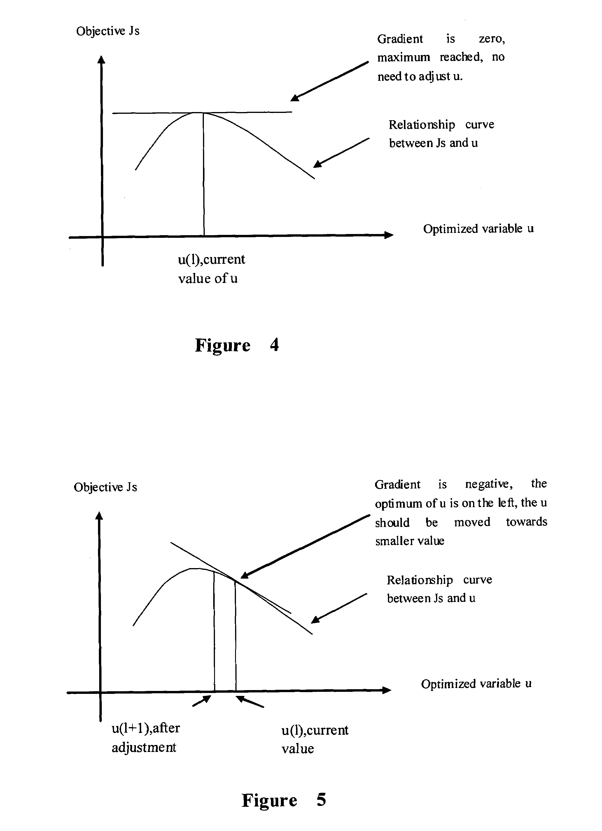
A real-time operating optimized method of multi-input and multi-output continuous manufacture procedure includes steps as follows: first, using plurality of pivotal operation conditions in the manufacture procedure as optimized variables, and using the technical target associating with the pivotal operation conditions as the objective function, then, calculating on line the grades vector between pivotal operation conditions and the technical target at current time according to historical data of pivotal operation conditions and the technical target, using correlation integral method or other methods, at last, using this grades vector to define the adjustment direction of the operation conditions. When the grades vector is positive or negative, the pivotal operation conditions should be adjusted in order to change the grades vector to zero.

Description

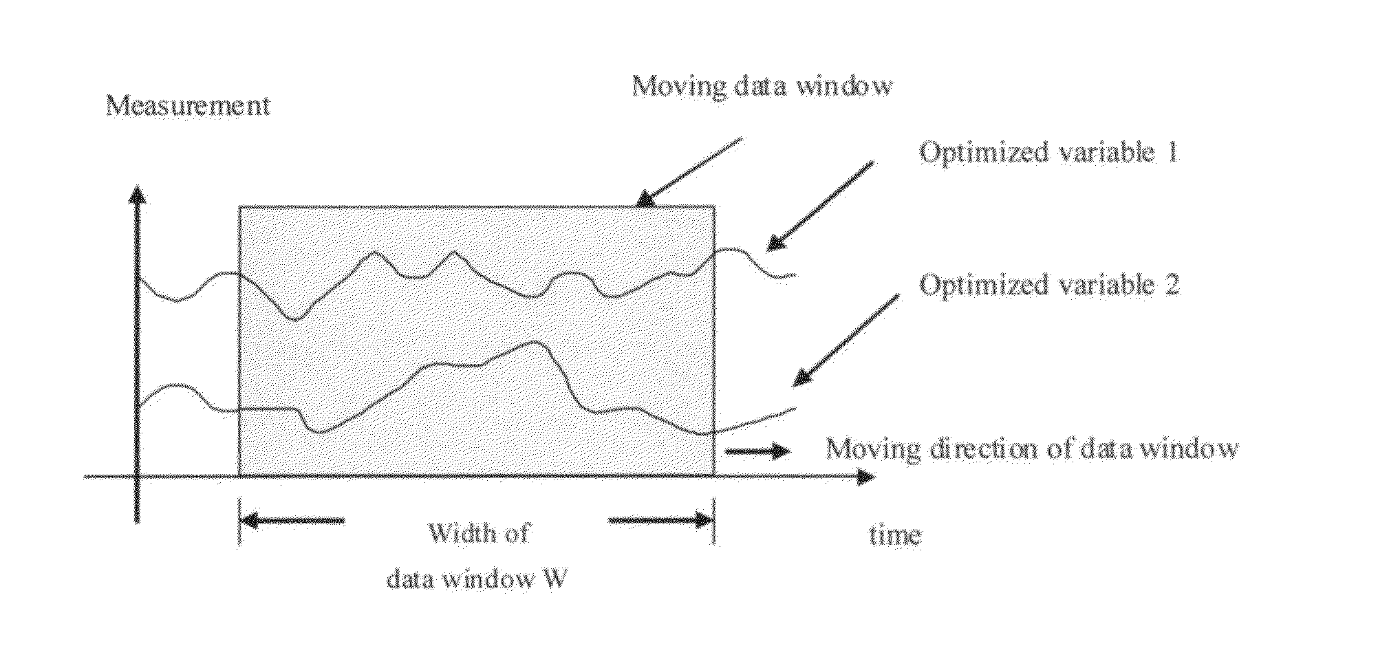
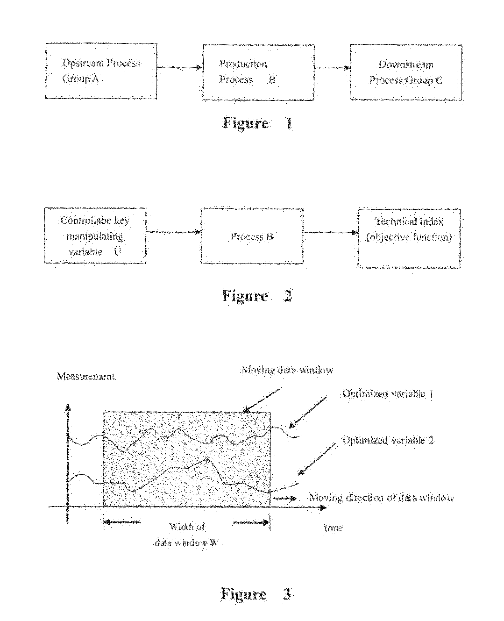
RELATED APPLICATIONS[0001]This application is the U.S. National Phase under 35 U.S.C. §371 of International Application No. PCT / CN2005 / 002324, filed on Dec. 27, 2005, which in turn claims the benefit of Chinese Application No. 200510085063.2, filed on Jul. 20, 2005, the disclosures of which Applications are incorporated by reference herein.TECHNICAL FIELD[0002]This invention relates to the control technique, and specifically, relates to a Real-Time Optimization (RTO) method of Multiple-Input and Multiple-Output (MIMO) continuous production process.BACKGROUND OF THE INVENTION[0003]A continuous production process with continuous feeds and output products could be illustrated as FIG. 1. In FIG. 1, A is the upstream unit group of process, and the products of A are the raw material of the process unit B, while the products of B are the raw material of downstream processing unit group C. Because the number of the kinds of products of B may be more than one and these products may be feed t...

Claims


Application Information

Patent Timeline
Patent Type & Authority Patents(United States)
IPC IPC(8): G05B13/02G06E3/00G06E1/00G06F7/60G06G7/00G06F15/18G06F17/10
CPCG05B11/42G05B2219/31265G05B2219/32015G05B19/41
Inventor WANG, JIAN
Owner WANG JIAN
Learn More