
Pipeline-based reconfigurable mixed-radix FFT processor

a processor and mixed-radix technology, applied in the field of processors, can solve the problems of long computation time and excessive hardware cost, only achieving 50% of the utilization rate of butterfly elements, and a large amount of computation time and hardware cost, so as to save computing time and hardware cos

Active Publication Date: 2010-12-07
NAT CHIAO TUNG UNIV
View PDF8 Cites 7 Cited by
  • Summary
  • Abstract
  • Description
  • Claims
  • Application Information

AI Technical Summary

Benefits of technology

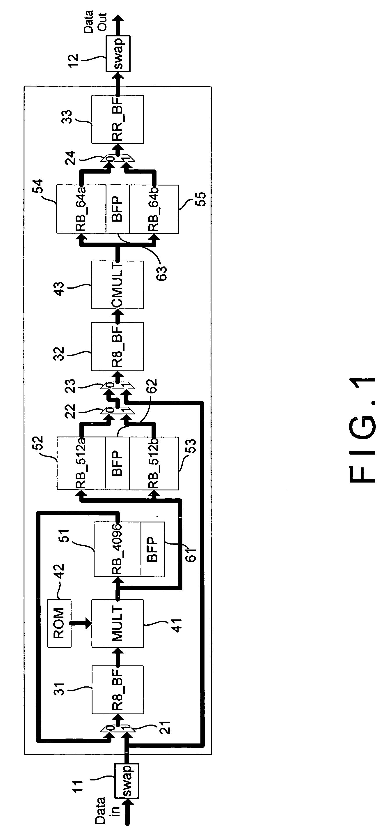
"The present invention is a pipeline-based reconfigurable mixed-radix FFT processor that aims to save computing time and hardware cost by decomposing N-point FFT into at most four computation stages. The processor includes a first commutator, a first multiplexer, a first general butterfly, a multiplier, a memory unit, a first register bank, a first Block Floating Point (BFP) unit, a second register bank, a second BFP unit, a second multiplexer, a second general butterfly, a coefficient multiplier, a fourth register bank, a fifth register bank, a third BFP unit, a fourth multiplexer, a reconfigurable butterfly, and a second commutator. The processor can be reconfigured to perform different operations and can be used in various applications such as wireless communication, image processing, and video compression."

Problems solved by technology

Yet, a computational complexity of direct evaluation of an N-point DFT is O(N2), which results in a long computation time and excessive hardware cost.
However, considerable symmetry exists in operations and coefficients required to compute a DFT.
However, a utilization rate of the butterfly elements [72] and multiplier units only achieves 50%.
However, more memory requirement and higher hardware complexity are the overhead in return.
The hardware complexity of the memory-based architecture concentrates on the control block [9].
Therefore, the memory-based architecture results in low through put rate.
However, such a reconfiguration requires lots of multiplexers when a higher flexibility is demanded in the FFT size.
Moreover, the multiplexers added between each stage not only increase the overhead on area and power, but also influence speed performance of the architecture.
Hence, the prior arts do not fulfill users' requests on actual use.

Method used


Image

  • Pipeline-based reconfigurable mixed-radix FFT processor
  • Pipeline-based reconfigurable mixed-radix FFT processor
  • Pipeline-based reconfigurable mixed-radix FFT processor

Examples


Embodiment Construction

[0043]The following description of the preferred embodiment is provided to understand the features and the structures of the present invention.

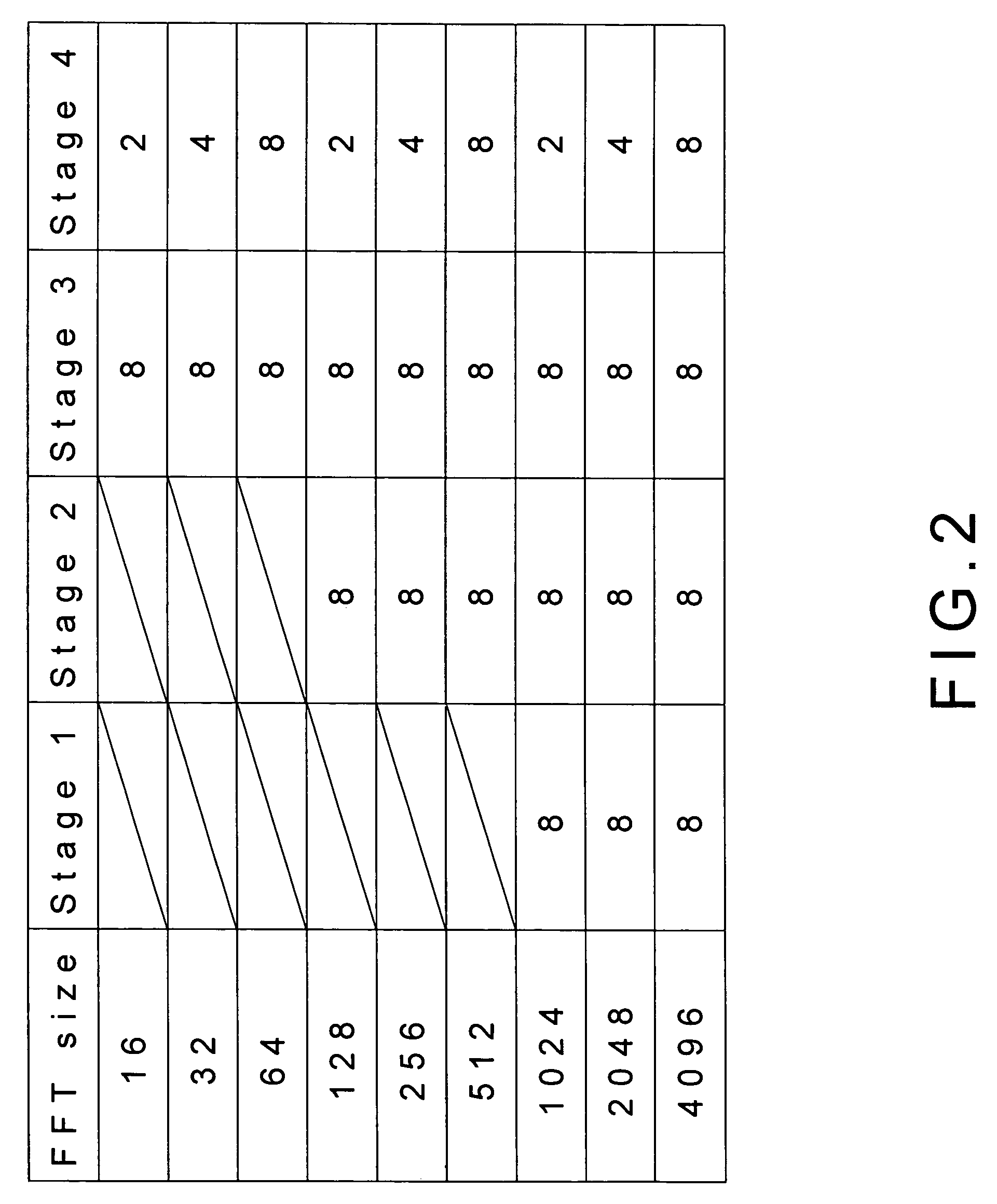
[0044]Please refer to FIG. 1 to FIG. 15 which, according to a preferred embodiment of the present invention, are a structural view and a block diagram of the preferred embodiment; views showing a block diagram of a 128-point fast Fourier transform (FFT) and a required number of storage elements for various N-point FFT; a view showing the circuit diagram of multiplication by 1 / √{square root over (2)}; views showing block diagrams of a general radix-8 butterfly and a reconfigurable butterfly; a view showing a relationship between control signals and the reconfigurable butterfly; views showing block diagrams of a two-input register and an RB_64 with various capacity; views showing data flows of an register bank for 16-word mode and 128-word mode; a view showing control zones of the register bank; and a view showing a block diagram of a reconfigu...


PUM


Abstract

The present invention discloses a fast Fourier transform (FFT) processor based on multiple-path delay commutator architecture. A pipelined architecture is used and is divided into 4 stages with 8 parallel data path. Yet, only three physical computation stages are implemented. The process or uses the block floating point method to maintain the signal-to-noise ratio. Internal storage elements are required in the method to hold and switch intermediate data. With good circuit partition, the storage elements can adjust their capacity for different modes, from 16-point to 4096-point FFTs, by turning on or turning off the storage elements.

Description

FIELD OF THE INVENTION[0001]The present invention relates to a processor; more particularly, relates to designing a fast Fourier transform processor in the digital signal processing domain.DESCRIPTION OF THE RELATED ARTS[0002]A discrete Fourier transform (DFT) is widely employed in analyses, designs, and implementations of signal processing algorithms and systems. Yet, a computational complexity of direct evaluation of an N-point DFT is O(N2), which results in a long computation time and excessive hardware cost. However, considerable symmetry exists in operations and coefficients required to compute a DFT. Such symmetry is exploited to reduce the number of operations required and thus reduces the time required for FFT computation. Collectively, the resulting efficient computation algorithms are called fast Fourier transform (FFT).[0003]Mainly, the FFT is a way of computing the DFT by decomposing the computation into successively smaller DFT computations. In this process, both the sy...

Claims


Application Information

Patent Timeline
Patent Type & Authority Patents(United States)
IPC IPC(8): G06F17/14
CPCG06F17/142
Inventor LAI, CHI-CHENHWANG, WEI
Owner NAT CHIAO TUNG UNIV
Learn More