Signal regeneration device, optical receiver, and signal processing method

a technology of signal regeneration and regeneration device, which is applied in the direction of digital transmission, electromagnetic transmission, phase-modulated carrier system, etc., can solve the problems of failure to provide any technique for enhancing the accuracy of the clock signal to be extracted, and the difficulty of detecting the accuracy of the clock signal to be detected, so as to improve the accuracy of the extracted clock signal and the effect of superior receiving sensitivity

Inactive Publication Date: 2010-12-14
FUJITSU LTD
View PDF16 Cites 4 Cited by
  • Summary
  • Abstract
  • Description
  • Claims
  • Application Information

AI Technical Summary

Benefits of technology

[0040]The present invention has been conceived in view of such problems, and is intended for enhancing the accuracy of a clock signal to be extracted while maintaining superior receiving sensitivity.
[0049]As mentioned above, according to the present invention, the branch section branches the electrical signal used for recovering a clock signal along with an electrical signal for regenerating data. Moreover, the waveform of one of the demodulated electrical signals branched by the branch section is equalized by means of an equalizing filter, and the clock recovery section can recover a clock signal from the demodulated electrical signal whose waveform has been equalized. Accordingly, there is yielded an advantage of the ability to enhance the accuracy of an extracted clock signal while maintaining superior receiving sensitivity.

Problems solved by technology

Therefore, when a change has arisen in a code, difficulty is encountered in detecting the edge, which in turn poses difficulty in enhancing the accuracy of a clock signal to be detected.
The related-art technology, including the techniques described in Patent Documents 1 to 3, fails to provide any technique for enhancing the accuracy of a clock signal to be extracted while maintaining such superior receiving sensitivity.

Method used


Image

  • Signal regeneration device, optical receiver, and signal processing method
  • Signal regeneration device, optical receiver, and signal processing method
  • Signal regeneration device, optical receiver, and signal processing method

Examples


Embodiment Construction

[0061]An embodiment of the present invention will be described hereinbelow by reference to the drawings.

[0062]In addition to the above-described object of the present invention, another technical drawback, means for solving the technical drawback, and a working effect thereof will become evident by the following disclosure of the present embodiment.

[A] Description of One Preferred Embodiment

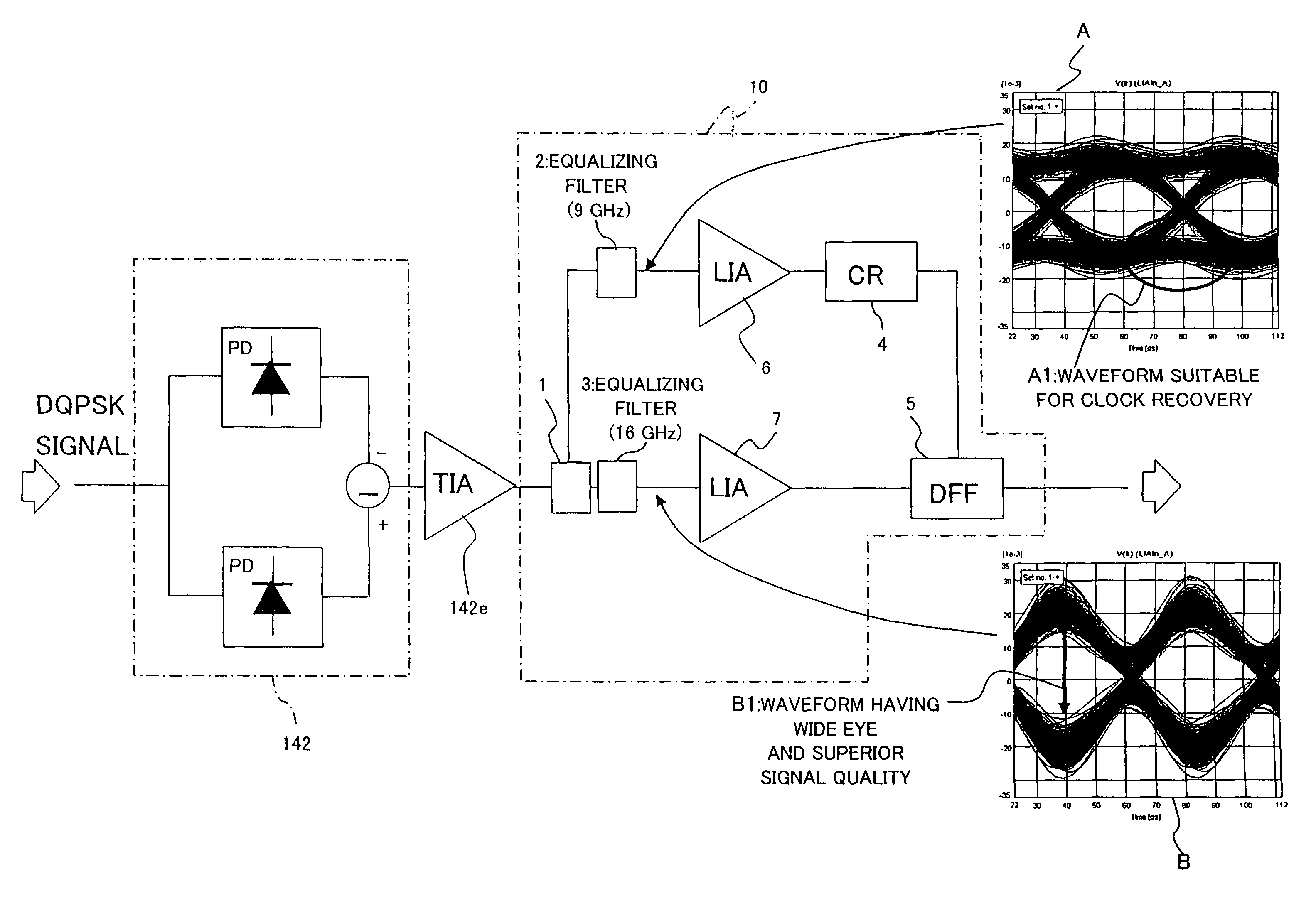
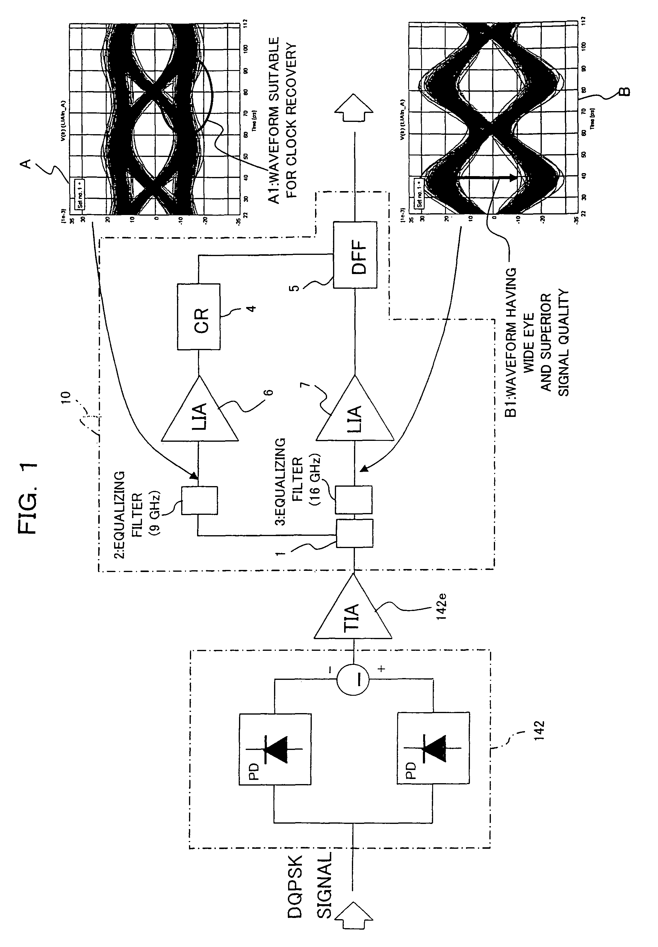
[0063]FIG. 1 is a block diagram showing a signal regeneration device 10. The signal regeneration device 10 shown in FIG. 1 is applied to the optical receiver of the optical transponder system adopting the (CS)RZ-DQPSK modulation-and-demodulation scheme shown in FIG. 9, and regenerates a data signal and a clock signal from the waveform of a received electrical signal which has been detected by means of photoelectric conversion. Put another way, two of the signal regeneration devices 10 are provided in place of the regeneration circuits 143-1, 143-2 (see FIG. 11) in the configuration of the optical...


PUM


Abstract

A signal regeneration device which makes an extracted clock signal highly accurate while maintaining superior receiving sensitivity. To this end, a device of the present invention is configured to have a branch section for branching an input electrical signal which has been demodulated from a differential phase-shift modulated state; a first filter for equalizing a waveform of one of the demodulated electrical signals branched by the branch section; a clock recovery section for recovering a clock signal from the demodulated electrical signal whose waveform has been equalized by the first filter; and a data regeneration section for regenerating a data signal from a remaining one of the demodulated electrical signals branched by the branch section and from a clock signal recovered by the clock recovery section.

Description

BACKGROUND OF THE INVENTION[0001]1) Field of the Invention[0002]The present invention relates to a signal regeneration device, an optical receiver, and a signal processing method suitably used for receiving a differential phase-shift keying modulated optical signal.[0003]2) Description of the Related Art[0004]Recently, there has been growing demand for introduction of a 40 Gbit / s optical transmission system as the next generation optical transmission system. Moreover, a transmission distance and a spectral efficiency, which are equal to those of a 10 Gbit / s system, are sought. Brisk research and development is being carried out, as means for achieving the transmission distance and the spectral efficiency, in relation to an RZ-DPSK (Differential Phase-Shift Keying) or a CSRZ-DPSK modulation scheme, which is superior to an NRZ (Non-Return to Zero) modulation scheme used in a conventional system of 10 Gb / s or less in terms of optical-signal-to-noise (OSNR) tolerance and non-linear tole...

Claims


Application Information

Patent Timeline
Patent Type & Authority Patents(United States)
IPC IPC(8): H04B10/02H04L27/01H04B10/516H04B10/548H04B10/556H04B10/58H04B10/61H04L27/22
CPCH04B10/66H04L25/03159H04L2025/03522
Inventor NISHIHARA, MASATOTAKAHARA, TOMOOISHIKAWA, GEORGE
Owner FUJITSU LTD
Why Eureka
Try Eureka