
Processing elements grouped in MIMD sets each operating in SIMD mode by controlling memory portion as instruction cache and GPR portion as tag

a processing element and mimd processing technology, applied in the field of processing elements, can solve the problems of increasing circuit scale, restricting the range of problems that may be tackled, etc., and achieve the effect of preventing the reduction of processing performance at the time of simd processing and not appreciably increasing circuit scal

Inactive Publication Date: 2010-12-14
NEC CORP
View PDF18 Cites 8 Cited by
  • Summary
  • Abstract
  • Description
  • Claims
  • Application Information

AI Technical Summary

Benefits of technology

The present invention provides a mixed mode parallel processor system and method that allows for efficient data exchange between processing elements in both SIMD and MIMD operations, without increasing the circuit scale and lowering the performance in MIMD processing. The system includes N processing elements that perform parallel operations in SIMD operation, and M sets of processing elements that perform parallel operations in MIMD operation. The system includes a control processing element for selecting instructions and a processing element for performing instruction cache control and instruction sequence control. The method allows for parallel operations in both SIMD and MIMD operations, and the system includes a control processing element for performing system control. The technical effects of the invention include improved processing performance and efficiency in data exchange between processing elements.

Problems solved by technology

However, the parallel processor of the SIMD system has a disadvantage that, since there is only one instruction stream, the range of problems that may be tackled with is necessarily restricted.
There is however a deficiency proper to the parallel processor of the MIMD system that it is in need of the same number of control circuits as the number of the PEs and hence is increased in circuit scale.

Method used


Image

  • Processing elements grouped in MIMD sets each operating in SIMD mode by controlling memory portion as instruction cache and GPR portion as tag
  • Processing elements grouped in MIMD sets each operating in SIMD mode by controlling memory portion as instruction cache and GPR portion as tag
  • Processing elements grouped in MIMD sets each operating in SIMD mode by controlling memory portion as instruction cache and GPR portion as tag

Examples


Embodiment Construction

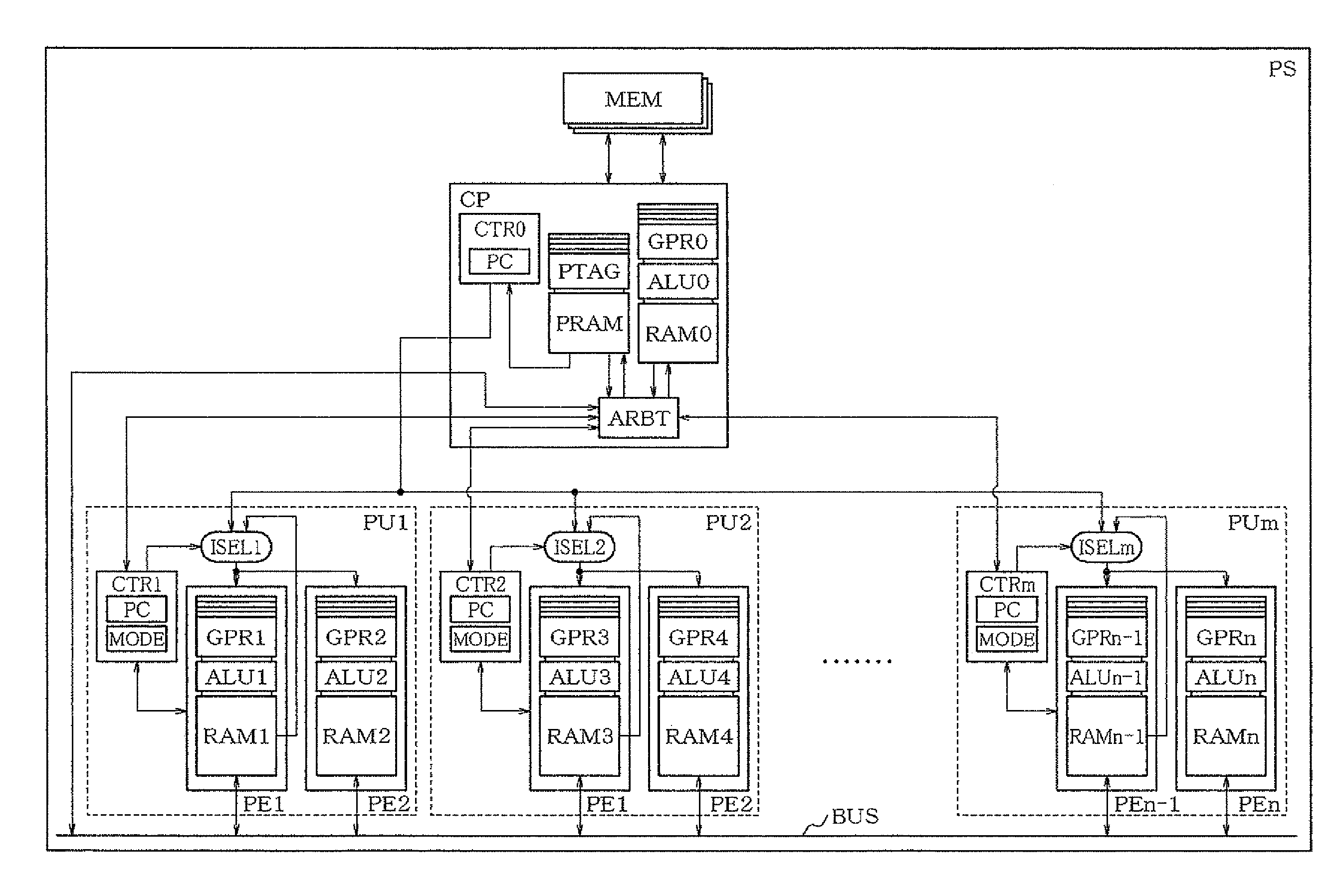
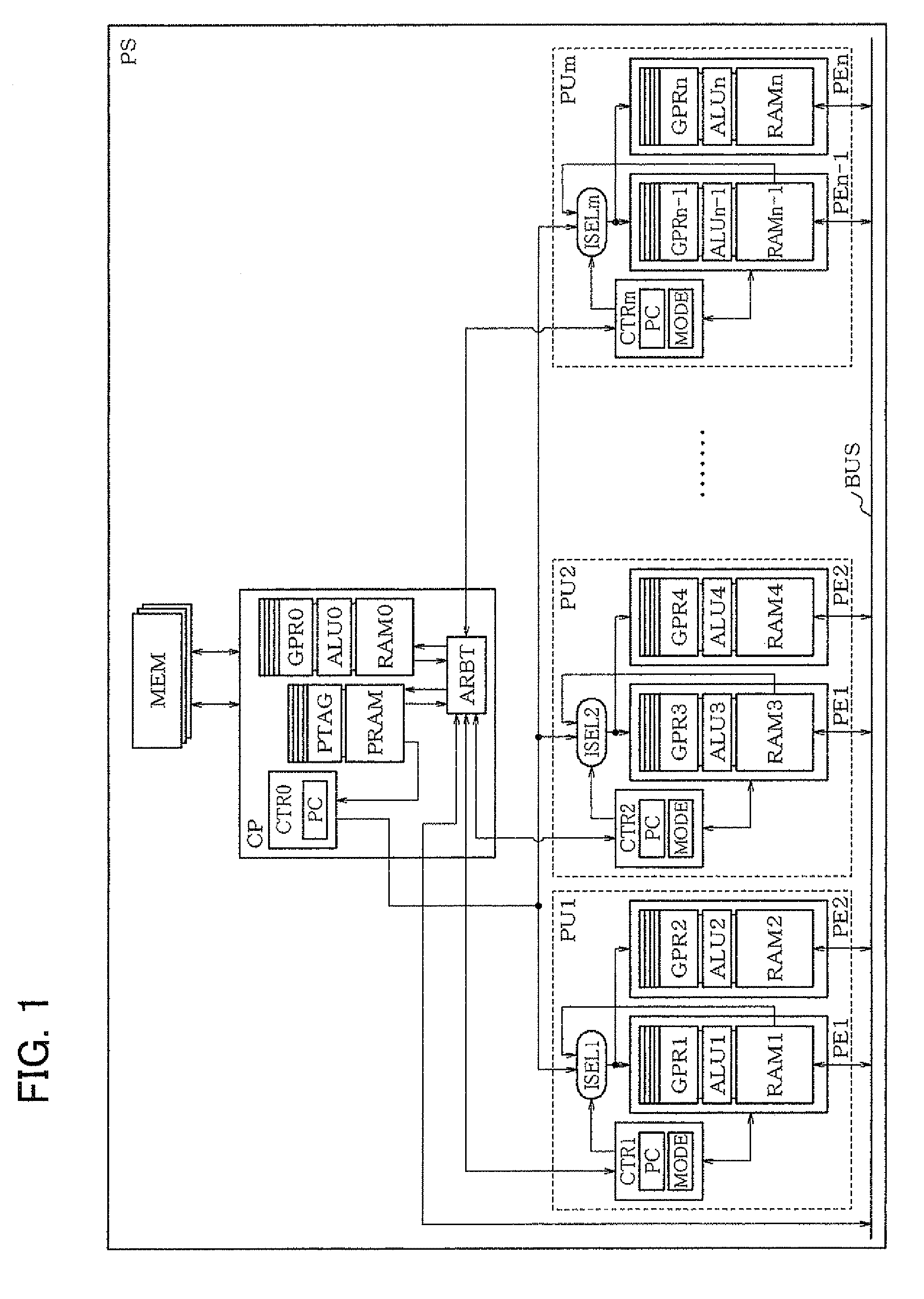
[0067]A mixed mode parallel processor system according to the present invention includes N number of processing elements PEs capable of performing SIMD operations. Each PE includes a memory (resource) and general-purpose registers (resources) for storing the temporary results of partial operation in the course of the arithmetic / logic operation. The mixed mode parallel processor system also includes M (=N÷S) instruction cache control circuits, not containing an instruction cache tag storage area, and M number of instruction sequence control circuits. It is noted that M, N and S are natural numbers.

[0068]A group consisting of S number of processing elements PEs, neighboring to each other, a sole instruction cache control circuit and a sole instruction sequence control circuit makes up a processing unit PU that performs MIMD operations. The instruction cache control circuit and the instruction sequence control circuit may also be included in the sole processing element PE.

[0069]In MIMD...


PUM


Abstract

Disclosed is a mixed mode parallel processor system in which N number of processing elements PEs, capable of performing SIMD operation, are grouped into M (=N÷S) processing units PUs performing MIMD operation. In MIMD operation, P out of S memories in each PU, which S memories inherently belong to the PEs, where P<S, operate as an instruction cache. The remaining memories operate as data memories or as data cache memories. One out of S sets of general-purpose registers, inherently belonging to the PEs, directly operates as a general register group for the PU. Out of the remaining S−1 sets, T set or a required number of sets, where T<S−1, are used as storage registers that store tags of the instruction cache.

Description

CROSS-REFERENCE TO RELATED APPLICATIONS[0001]This invention is based on Convention rights pertaining to JP Patent Application No. 2006-225963 filed on Aug. 23, 2006. The entire disclosure of this Patent Application is to be incorporated herein by reference thereto.TECHNICAL FIELD[0002]The present invention relates to processing elements, a mixed mode parallel processor system, a processing method by processing elements, a mixed mode parallel processor method, a processor program by processing elements and a mixed mode parallel processor program. More particularly, it relates to processing elements, a mixed mode parallel processor system, a processing method by processing elements, a mixed mode parallel processor method, a processor program by processing elements and a mixed mode parallel processor program of higher efficiency.BACKGROUND ART[0003]There has so far been proposed a parallel processor of the so-called SIMD (Single Instruction Multiple Data) system, in which larger number...

Claims


Application Information

Patent Timeline
Patent Type & Authority Patents(United States)
IPC IPC(8): G06F15/80
CPCG06F15/80G06F9/46G06F12/08
Inventor KYO, SHORIN
Owner NEC CORP
Learn More