
Application of microsystems for comfort control

a microsystem and comfort control technology, applied in the field of indoor environmental control, can solve the problems of limiting the application of the combined heat/humidity index in the building control or hvac industry, and hindering such applications, and achieve the effect of reducing labor and material costs

Active Publication Date: 2010-12-21
SIEMENS IND INC
View PDF28 Cites 188 Cited by
  • Summary
  • Abstract
  • Description
  • Claims
  • Application Information

AI Technical Summary

Benefits of technology

[0012]In other embodiments, some or all of the microsystems need not be wireless. However, there is an advantage to the use of wireless microsystems because it reduces labor and material costs associated with running wires.

Problems solved by technology

As yet, however, there has been limited application of the combined heat / humidity index in the building control or HVAC industry.
Costs related to sensing both temperature and relative humidity on a comprehensive scale has hindered such applications.

Method used


Image

  • Application of microsystems for comfort control
  • Application of microsystems for comfort control
  • Application of microsystems for comfort control

Examples


Embodiment Construction

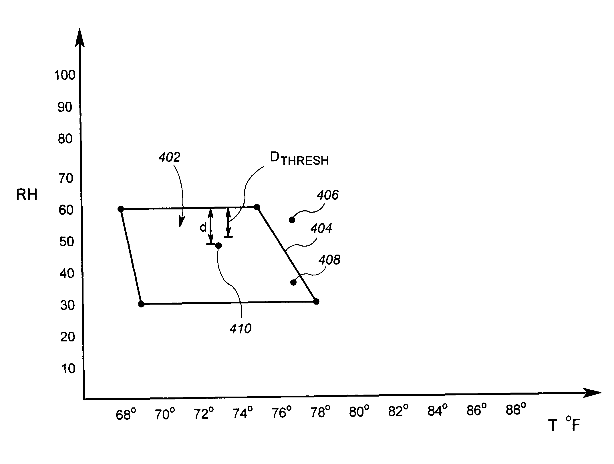
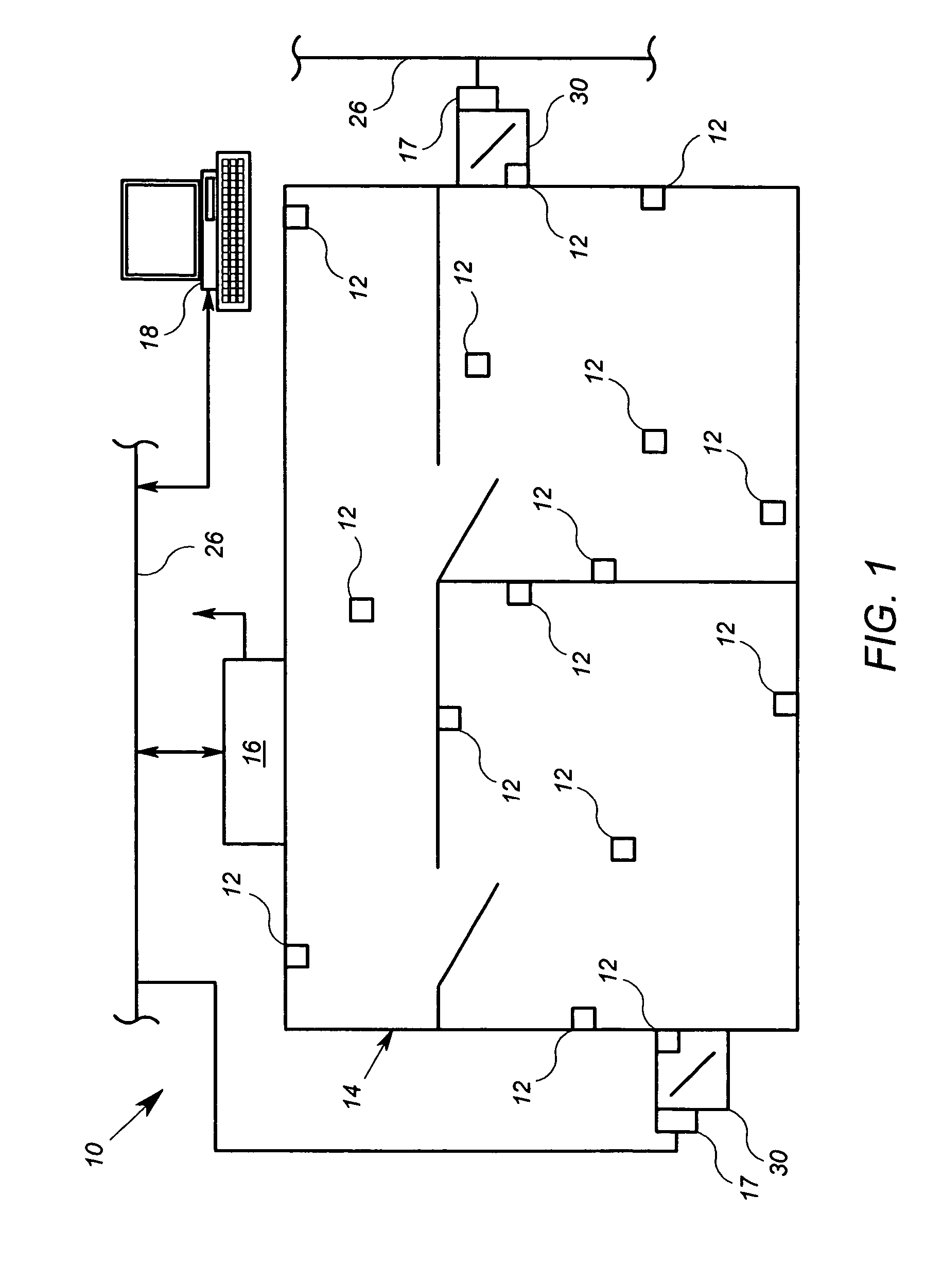
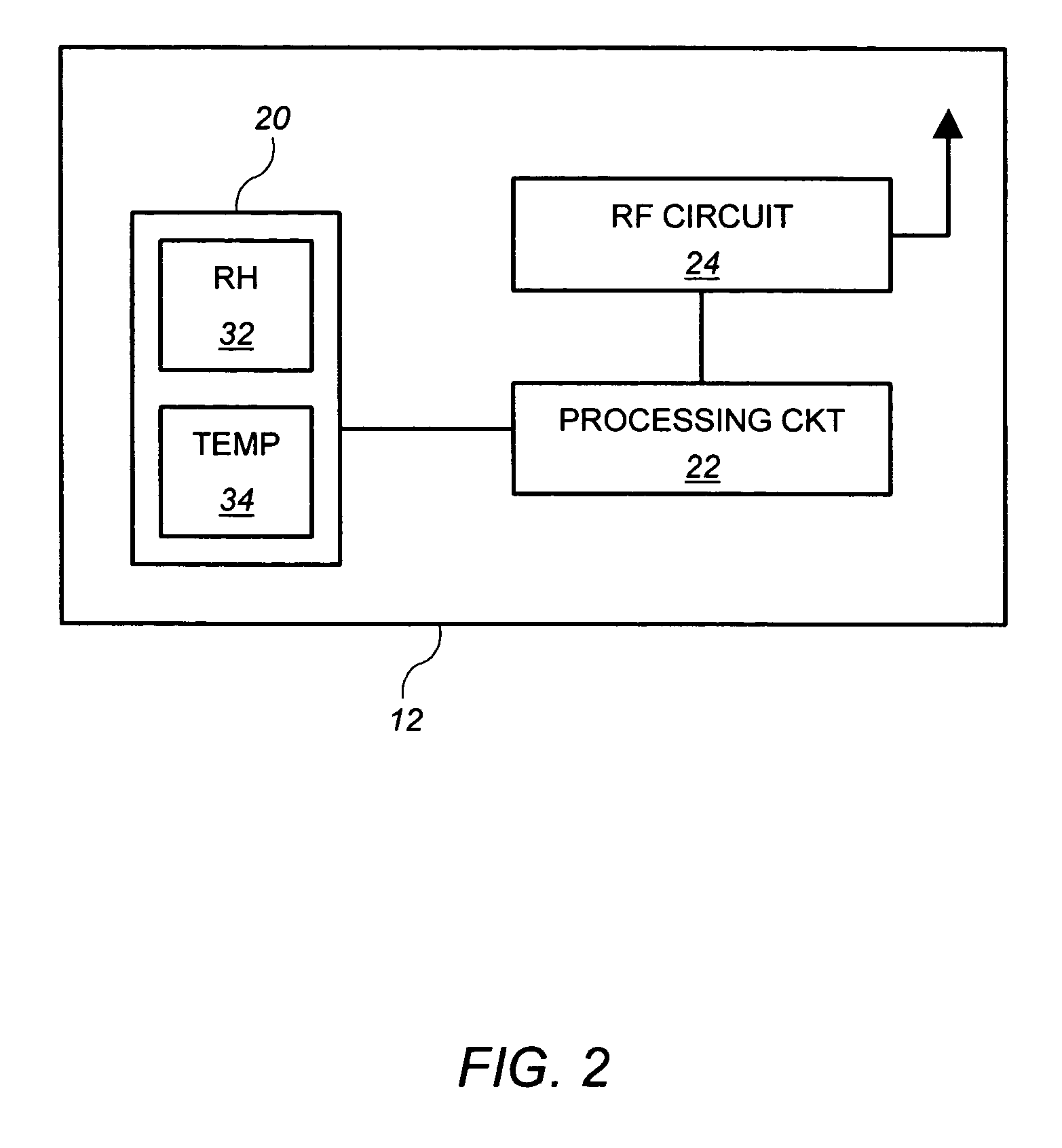
[0019]FIG. 1 shows an arrangement 10 that includes a plurality of wireless microsystems 12, each microsystem 12 is operable to measure at least relative humidity and temperature parameters in a building environment 14 and is further operable to communicate the parameters (either individually, or combined to form a comfort index) wirelessly to a network device 16. The network device 16 is operable to communicate the comfort index information from the plurality of microsystems 12 to room controllers 17. The room controllers 17 are operable to generate control signals that cause ventilation shaft dampers 30 to further open or close in order to adjust the flow of supply air (which may be heated or chilled), into the various rooms of the building environment 14.

[0020]The comfort index is a variable representative of a theoretical comfort level based on relative humidity and temperature. It is known that the same temperature may feel comfortable at 50% relative humidity, but less comforta...


PUM


Abstract

An arrangement includes a plurality of wireless microsystems. Each microsystem is operable to measure at least relative humidity and temperature, and to communicate temperature and relative humidity information wirelessly to a network device. The network device is operable to communicate the temperature and relative humidity information to at least a first processor configured to cause a change in a building control condition based on the information.

Description

[0001]This application claims the benefit of U.S. Provisional Patent Application Ser. No. 60 / 713,042, filed Aug. 30, 2006, which is incorporated herein by reference.FIELD OF THE INVENTION[0002]The present invention relates to indoor environmental control, and more particularly to HVAC control based at least in part on relative humidity and temperature.BACKGROUND[0003]Buildings in which people work and live have systems that monitor and sustain the comfort level of the building environment. Such systems include heating, ventilation and air conditioning (HVAC) systems, lighting systems, as well as others. HVAC and lighting systems have existed, at least at some level, for thousands of years.[0004]HVAC and lighting systems have become sophisticated, and are often able to maintain careful balances of humidity and temperature, as well as provide fresh air and adequate light within buildings. Suitable temperature, humidity, light and oxygen levels contribute to the indoor environmental qu...

Claims


Application Information

Patent Timeline
Patent Type & Authority Patents(United States)
IPC IPC(8): F24F3/14F25B49/00G01M1/00G05D23/00
CPCF24F11/0008F24F11/006G05B15/02F24F11/0012F24F11/0015F24F2011/0057F24F2011/0068F24F11/30F24F2110/10F24F2110/20F24F2120/20F24F11/62F24F11/56F24F11/76F24F11/46F24F11/63
Inventor AHMED, OSMAN
Owner SIEMENS IND INC
Learn More