Magnetron with relatively fixed yoke and cooling block by means of a cushioning material and fixing member

a cooling block and relatively fixed yoke technology, applied in the field of magnets, to achieve the effect of stable operation, reducing cost, and improving impact resistance and vibration resistan

Inactive Publication Date: 2010-12-21
PANASONIC CORP
View PDF7 Cites 4 Cited by
  • Summary
  • Abstract
  • Description
  • Claims
  • Application Information

AI Technical Summary

Benefits of technology

[0015]The present invention is devised by considering the above-described circumstances, and it is an object of the present invention to provide a magnetron that is excellent in its impact resistance and vibration resistance and easy in its assembly even when there is unevenness in dimension of a cooling block or a magnetic yoke and hardly generates a corrosion of metal.

Problems solved by technology

Further, since the gap is provided between the cooling block and the magnetic yoke, even when there is dimensional unevenness in the cooling block or the magnetic yoke, the above-described cushioning material absorbs it.

Method used


Image

  • Magnetron with relatively fixed yoke and cooling block by means of a cushioning material and fixing member
  • Magnetron with relatively fixed yoke and cooling block by means of a cushioning material and fixing member
  • Magnetron with relatively fixed yoke and cooling block by means of a cushioning material and fixing member

Examples


Embodiment Construction

[0046]Now, a preferred embodiment for embodying the present invention will be described below in detail by referring to the drawings.

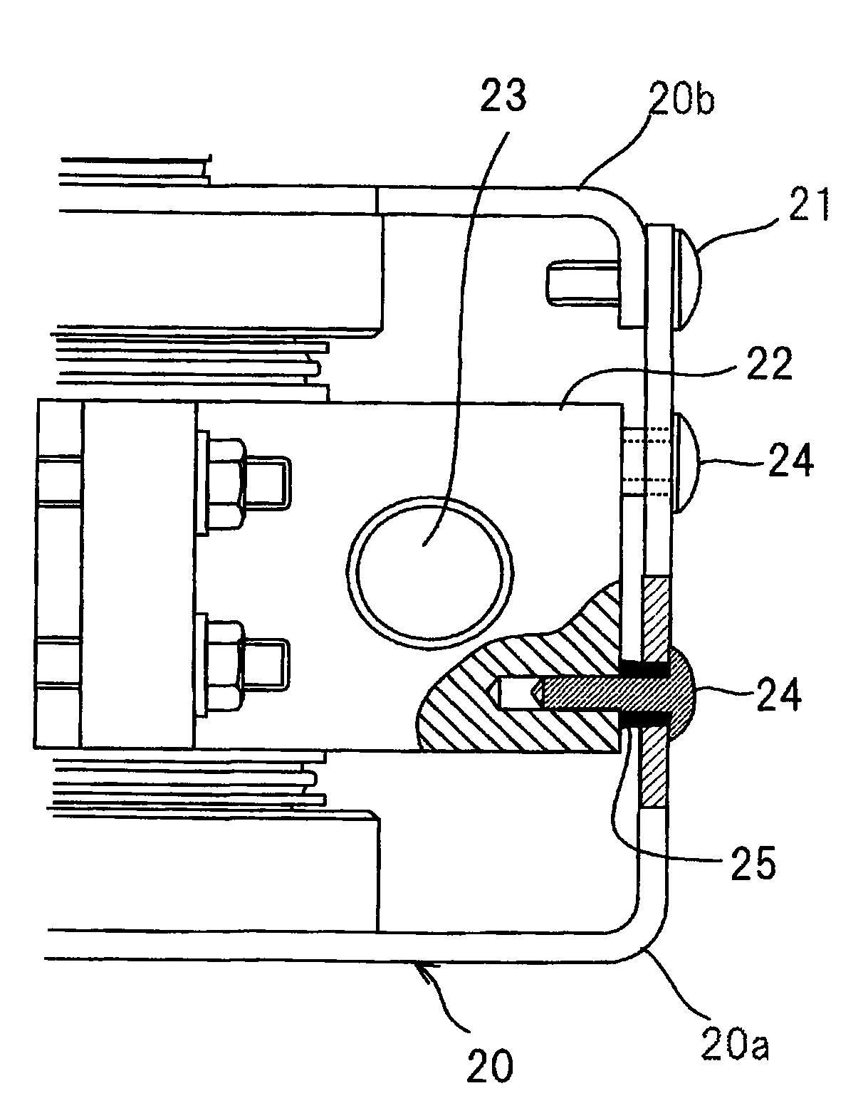
[0047]FIG. 1 is a side view showing a magnetron according to one embodiment of the present invention. In FIG. 1, parts the same as those of FIG. 17 are designated by the same reference numerals. Further, in FIG. 1, an inner part of a magnetic yoke 20 is seen so that the relation between the magnetic yoke 20 and a cooling block 22 can be easily understood. The magnetic yoke 20 has a substantially same structure as that of the above-described magnetic yoke 4 shown in FIG. 17. However, a positional relation of a main body part 20a and a cover part 20b of the magnetic yoke 20 is inverted. That is, the magnetic yoke 20 includes the main body part 20a with a form having one end (an upper end in FIG. 1) opened, the other end (a lower end in FIG. 1) closed and a hole (an illustration is omitted) opened at a central part and the cover part 20b for closing the o...


PUM


Abstract

A gap is provided between a cooling block 22 and a magnetic yoke 20. A cushioning material 25 is interposed in the gap to fix the cooling block 22 relatively to the magnetic yoke 20 by screws. Thus, even when metals having a large difference in tendency of ionization are used in the cooling block 22 and the magnetic yoke 20, the corrosion of the metals hardly arises. Further, the cushioning material 25 is provided in the gap between the cooling block 22 and the magnetic yoke 20, so that an impact or vibration to an anode tubular member 10 can be mitigated and the disconnection and deficiency of the filament of a cathode structural member can be reduced. Further, since a dimensional unevenness of the cooling block 22 or the magnetic yoke 20 can be absorbed by the cushioning material 25, the dimensional accuracy of parts does not need to be improved to make an assembly easy.

Description

BACKGROUND OF THE INVENTION[0001]1. Field of the Invention[0002]The present invention relates to a magnetron preferably applied to a device using a microwave such as a microwave oscillator.[0003]2. Description of the Related Art[0004]FIG. 17 is a longitudinally sectional view showing a magnetron disclosed in Patent Document 1. The magnetron shown in FIG. 17 mainly includes a magnetic yoke 4, an output part 9 provided in the upper part of the magnetic yoke 4 and a filter 11 provided in the lower part of the magnetic yoke 4. In the magnetic yoke 4, two annular permanent magnets 8A and 8B, an anode tubular member 10 and a cooling block 1 for covering the periphery of the anode tubular member 10 are accommodated. The filter 11 is provided with a choke coil 6 and a through capacitor 7.[0005]The magnetic yoke 4 includes a main body part 4a with a form having one end (a lower end in FIG. 17) opened, the other end (an upper end in FIG. 17) closed and a hole (an illustration is omitted) open...

Claims


Application Information

Patent Timeline
Patent Type & Authority Patents(United States)
IPC IPC(8): H01J1/50H01J25/50H01J7/24
CPCH01J23/005H01J23/12H01J25/50
Inventor HANDA, TAKANORI
Owner PANASONIC CORP
Why Eureka
Try Eureka