One-piece heart prosthesis implantable in an anatomical position

a one-piece, anatomical technology, applied in the field of one-piece heart prosthesis implantable in anatomical position, can solve the problems of difficulty and overall size of said prosthesis, and achieve the effect of reducing its size and facilitating the placement of the prosthesis

Active Publication Date: 2010-12-28
CARMAT CO LTD
View PDF6 Cites 0 Cited by
  • Summary
  • Abstract
  • Description
  • Claims
  • Application Information

AI Technical Summary

Benefits of technology

[0011]Thus, by virtue of the present invention, the offset positioning of said individual hydraulic actuators and the asymmetrical V-shaped arrangement of said artificial ventricles make it possible to position the blood compartments opposite the corresponding natural auricles while at the same time giving said prosthesis a shape and a volume close to the anatomical shape and volume of the pericardial cavity, thereby allowing said prosthesis to be lodged in said cavity.
[0014]In order to further enhance the beneficial effects afforded by the invention, it is advantageous that the dimensions of said artificial ventricles, parallel to said general directions, are smaller than the dimensions of said ventricles perpendicular to said general directions, and that the general directions of the two artificial ventricles form between them an angle at least approximately equal to 80°.
[0018]In a general manner, the asymmetrical and overlapping arrangement of the ventricles and of the hydraulic actuators, which constitutes one of the original features of said heart prosthesis, makes it possible to reduce its size as far as possible, thereby making it easier to lodge the prosthesis in the pericardial cavity.
[0023]a flexible pouch surrounding, amply and sealingly, at least part of said rigid body by enclosing said hydraulic actuators and the electronics for control, signal processing and communication, said pouch being filled with said hydraulic fluid and serving as a container for the hydraulic circuit of said actuators. Said pouch, being very wide, is driven by beats of low amplitude, which thus avoids the need for a compliance chamber remote from the prosthesis. Moreover, by surrounding the actuators and the control electronics, said pouch protects these and facilitates heat exchange between actuators, ventricular chambers and adjacent tissues; and

Problems solved by technology

This has the result that the overall size of said prosthesis is not optimal and that difficulties may arise during implantation in the thoracic and pericardial cavity of many patients.

Method used


Image

  • One-piece heart prosthesis implantable in an anatomical position
  • One-piece heart prosthesis implantable in an anatomical position
  • One-piece heart prosthesis implantable in an anatomical position

Examples


Embodiment Construction

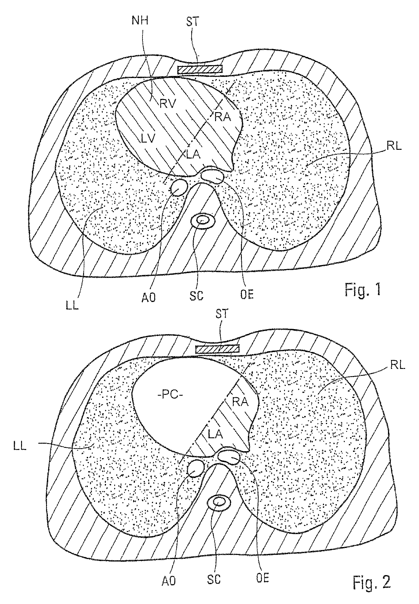
[0036]The cross section of the thorax shown schematically in FIG. 1 depicts the left lung LL, the right lung RL, the sternum ST, the aorta AO, the spinal cord SC, the oesophagus OE and the natural heart NH of a patient. On this natural heart, the left auricle LA, the right auricle RA, the left ventricle LV and the right ventricle RV are depicted.

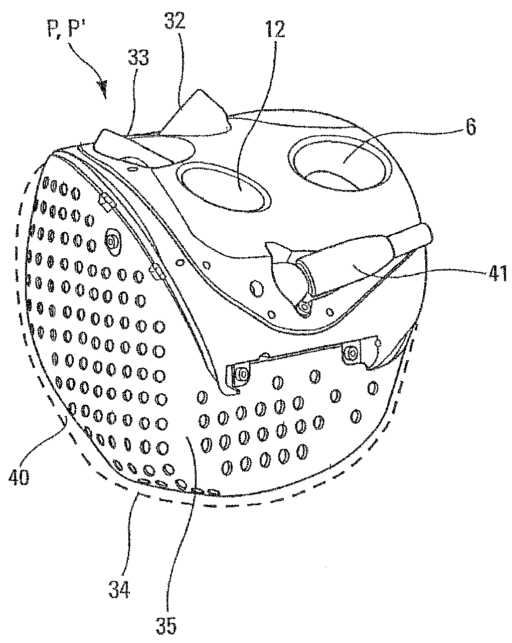
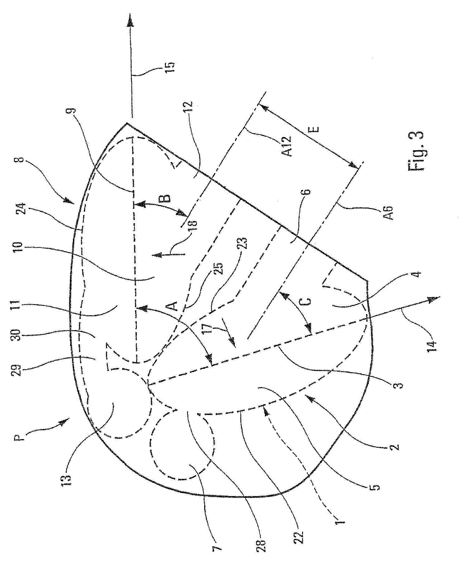
[0037]The heart prostheses P and P′ according to the present invention, shown schematically and on an enlarged scale in FIGS. 3 and 5, respectively, are designed to replace the left and right ventricles LV and RV, after their removal, as is illustrated schematically in FIG. 2. To do this, the heart prostheses P and P′ must be able to be lodged in the part of the pericardial cavity PC left free by the removal of said ventricles LV and RV (see FIGS. 2 and 4).

[0038]As is shown schematically in FIGS. 3, 5 and 9, the heart prostheses P and P′ comprise a rigid body 1, in which are arranged:[0039]an artificial left ventricle 2 comprising a flexible...


PUM


Abstract

One-piece heart prosthesis implantable in an anatomical position. According to the invention, the artificial left and right ventricles (2, 8) have general directions (14, 15) arranged in an asymmetrical V shape, such that said ventricles approach each other as they move away from the means (6, 12) of connection to the natural left and right auricles, and the individual hydraulic actuators (7, 13), associated respectively with said artificial left and light ventricles (2, 8), are arranged near each other, in proximity to said artificial left ventricle (2).

Description

TECHNICAL FIELD OF THE INVENTION[0001]The present invention relates to a one-piece heart prosthesis implantable in an anatomical position.BACKGROUND OF THE INVENTION[0002]Document U.S. Pat. No. 5,135,539 has already disclosed a heart prosthesis which is implantable in the pericardial cavity of a patient and which is able to replace the natural left and right ventricles of said patient after their removal. This heart prosthesis comprises a rigid body in which artificial left and right ventricles are arranged, each of these artificial ventricles comprising a flexible membrane:[0003]which is able to beat under the action of a hydraulic fluid, and[0004]which is arranged in a cavity divided in a leaktight manner by said membrane into two chambers, one of which is intended for the circulation of the blood, and the other of which is filled with said hydraulic fluid.[0005]Furthermore, the hydraulic fluid chamber of each of said artificial ventricles is connected to an individual hydraulic a...

Claims


Application Information

Patent Timeline
Patent Type & Authority Patents(United States)
IPC IPC(8): A61M1/10
CPCA61M1/106A61M60/148A61M60/554A61M60/531A61M60/405A61M60/165
Inventor GRIMME, MARCKOECHLER, MAURICEPARQUET, JEAN-MARCCARPENTIER, ALAIN
Owner CARMAT CO LTD
Why Eureka
Try Eureka