Combustion systems and power plants incorporating parallel carbon dioxide capture and sweep-based membrane separation units to remove carbon dioxide from combustion gases

a technology of combustion gas and carbon dioxide capture, which is applied in the direction of machine/engine, separation process, lighting and heating apparatus, etc., can solve the problems of power plants generating enormous amounts of flue gas, and achieve the effect of reducing the environmental impact of discharging this stream and good carbon dioxide removal

Inactive Publication Date: 2011-10-11
MEMBRANE TECH & RES
View PDF23 Cites 17 Cited by
  • Summary
  • Abstract
  • Description
  • Claims
  • Application Information

AI Technical Summary

Benefits of technology

[0018]The combustion systems and power plants of the invention are configured to treat the exhaust gas to remove carbon dioxide. In preferred embodiments, the carbon dioxide level of the exhaust gas is reduced to as low as 5 vol % or less, and most preferably, to 3 vol % or less. Discharge of such a stream to the environment is much less damaging than discharge of the untreated exhaust.
[0046]Many membrane materials are very permeable to water vapor, so the permeate stream from the membrane unit will tend to contain high concentrations of water vapor, such as 20 vol %, 30 vol %, or more. The co-permeation of water with the carbon dioxide is helpful, as the water dilutes the carbon dioxide concentration on the permeate side and helps maintain driving force for transmembrane permeation for carbon dioxide.
[0047]Optionally, the beneficial effect of copermeation of water can be maintained or enhanced by adding water vapor to the first membrane feed stream if it is not saturated, or by injecting steam or water vapor between the individual membrane modules, especially towards the residue end of the train of modules.
[0053]The second portion of the exhaust stream from the combustion unit flows across the feed side of the membranes in the sweep unit, and a sweep gas of air, oxygen-enriched air, or oxygen flows across the permeate side, to provide or augment the driving force for transmembrane permeation. It is highly preferred that the feed gas flow direction across the membrane on the feed side and the sweep gas flow direction across the membrane on the permeate side are substantially countercurrent to each other. In the alternative, the relative flow directions may be substantially crosscurrent or, less preferred, cocurrent. Additionally, the process may be augmented by operating the membrane unit with higher total pressure on the feed side than on the permeate side, thereby increasing the transmembrane driving force for permeation.
[0055]By using the oxygen-containing stream destined for the combustion unit as sweep gas, the membrane separation step is carried out in a very efficient manner, and without introducing any additional unwanted components into the combustion unit. Further, circulation of the permeate stream back to the combustion unit is advantageous, as it helps to build up the carbon dioxide concentration that passes to the carbon dioxide capture unit, facilitating good carbon dioxide removal.
[0056]The residue (vent) stream from the membrane unit is reduced in carbon dioxide content to less than about 5 vol %, more preferably to less than 3 vol % and, most preferably, to less than 2 vol %. This stream is typically, although not necessarily, discharged to the environment. The reduction of the carbon dioxide content to 20 vol %, 10 vol %, or less of the content in the raw exhaust stream significantly reduces the environmental impact of discharging this stream.

Problems solved by technology

In particular, power plants generate enormous amounts of flue gas.

Method used


Image

  • Combustion systems and power plants incorporating parallel carbon dioxide capture and sweep-based membrane separation units to remove carbon dioxide from combustion gases
  • Combustion systems and power plants incorporating parallel carbon dioxide capture and sweep-based membrane separation units to remove carbon dioxide from combustion gases
  • Combustion systems and power plants incorporating parallel carbon dioxide capture and sweep-based membrane separation units to remove carbon dioxide from combustion gases

Examples


example 1

Bases of Calculations for Other Examples

[0132](a) Membrane permeation experiments: Sets of permeation experiments were performed with two different composite membranes, each having a polyether-based selective layer. The properties of the membranes as measured with a set of pure gases at 6.7 bar absolute and 30° C. are shown in Tables 1 and 2.

[0133]

TABLE 1GasPermeance (gpu)*CO2 / Gas SelectivityCarbon dioxide1,000—Nitrogen  2050Oxygen  5020Methane  5020Water >2,000**—*Gas permeation unit; 1 gpu = 1 × 10⁻⁶ cm3(STP) / cm2 · s · cmHg**Estimated, not measured

[0134]The following calculations were performed using the membrane properties shown in Table 2.

[0135]

TABLE 2GasPermeance (gpu)*CO2 / Gas SelectivityCarbon dioxide1,000—Nitrogen  3033Oxygen  6017Hydrogen  10010Water 5,000**—*Gas permeation unit; 1 gpu = 1 × 10⁻⁶ cm3(STP) / cm2 · s · cmHg**Estimated, not measured

[0136](b) Calculation methodology: The computer calculations in all of the following Examples were performed using a modeling program...

examples 2-8

Embodiments of the Invention: Modeling of Sweep-Based Membrane Separation Step and Effect on Combustion Step

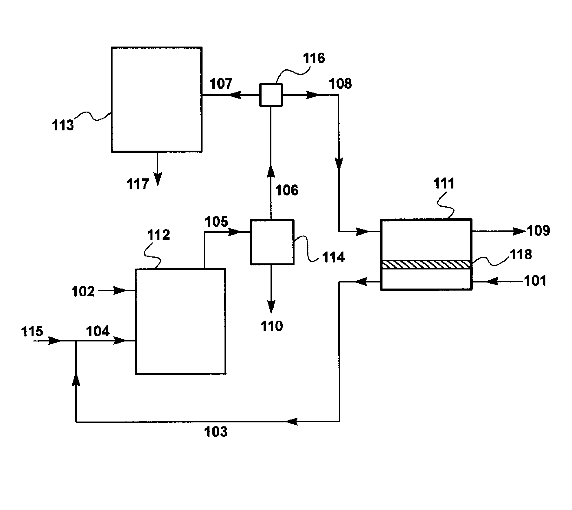
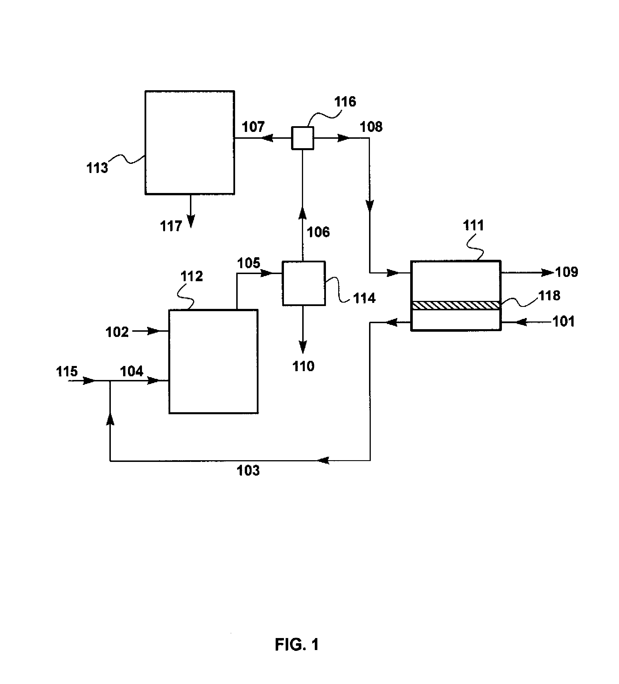
[0142]A set of calculations was performed to model the effect of various process parameters on the performance of the sweep-based membrane separation step and its effect on the combustion step. The calculations for Examples 2 through 8 were performed using the flow scheme shown in FIG. 1 and described in the Detailed Description, above. This flow scheme includes a sweep-based membrane separation step, 111.

[0143]To facilitate operation of the calculation software, the base case air flow provided to the combustor via the membrane permeate side was assumed to be about 740 m3 / h (950 kg / h), compared with the typical air flow to a 500 MW power plant of about 1.8 million m3 / h used for the calculation of Example 1. In other words, the scale of the calculations for Examples 2 through 8 was about 1 / 2,400 of the scale for a typical coal-fired power plant. This reduces membrane area propo...

example 2

Embodiment of the Invention

[0144]In this example, the membrane area was assumed to be 400 m2, and the combustion exhaust stream split ratio was set at 1:1 (flow to carbon dioxide capture step:flow to sweep-based membrane separation step). The separation was assumed to be performed using a membrane having permeation properties as in Table 2. The results of this calculation are shown in Table 4.

[0145]

TABLE 4Gas toCondenserCaptureMembraneAirGas toCoalKnockoutStepFeedSweepCombustorRetentateParameter / Stream(102)(110)(107)(108)(101)(103)(109)Total Flow (kg / h)55465545549501100404Temperature (° C.)25404040253325Pressure (bar)1.01.01.01.01.01.01.0Component (vol %)Coal (carbon +100000000hydrogen)Oxygen001.61.621.017.55.2Nitrogen0071.871.879.070.691.9Carbon Dioxide0019.219.208.32.9Water01007.47.403.60

[0146]Compared with the “no membrane” Example 1, the carbon dioxide content in the combustion exhaust stream 107 sent to the capture step is increased from 11.7 vol % to 19.2 vol %, and compared t...


PUM

PropertyMeasurementUnit
vol %aaaaaaaaaa
pressureaaaaaaaaaa
areaaaaaaaaaaa

Abstract

Disclosed herein are combustion systems and power plants that incorporate sweep-based membrane separation units to remove carbon dioxide from combustion gases. In its most basic embodiment, the invention is a combustion system that includes three discrete units: a combustion unit, a carbon dioxide capture unit, and a sweep-based membrane separation unit. In a preferred embodiment, the invention is a power plant including a combustion unit, a power generation system, a carbon dioxide capture unit, and a sweep-based membrane separation unit. In both of these embodiments, the carbon dioxide capture unit and the sweep-based membrane separation unit are configured to be operated in parallel, by which we mean that each unit is adapted to receive exhaust gases from the combustion unit without such gases first passing through the other unit.

Description

[0001]This application claims the benefit of U.S. Provisional Application Ser. No. 61 / 127,415, filed May 12, 2008, PCT Application No. PCT / US09 / 02874, filed May 8, 2009; U.S. application Ser. No. 12 / 734,941, filed Jun. 2, 2010; and U.S. application Ser. No. 12 / 807,846, filed Sep. 13, 2010, the disclosures of which are hereby incorporated herein by reference in their entireties.[0002]This invention was made in part with U.S. Government support under SBIR Award No. DE-NT-000-5312, awarded by the U.S. Department of Energy. The U.S. Government has certain rights in this invention.FIELD OF THE INVENTION[0003]The invention relates to combustion systems and power plants that incorporate sweep-based membrane separation units to remove carbon dioxide from combustion gases.BACKGROUND OF THE INVENTION[0004]In a traditional power generation process, a fuel (such as coal, natural gas, or syngas) is combusted in the presence of oxygen, producing a stream of hot, high-pressure gas. This hot, high-...

Claims


Application Information

Patent Timeline
Patent Type & Authority Patents(United States)
IPC IPC(8): B01D53/22
CPCB01D53/225B01D53/229B01D2257/504Y02C10/10Y02C20/40
Inventor WIJMANS, JOHANNES G.MERKEL, TIMOTHY CBAKER, RICHARD W.
Owner MEMBRANE TECH & RES
Why Eureka
Try Eureka