Imaging device and driving method thereof

a technology of driving method and imaging device, which is applied in the direction of radio frequency controlled devices, television system scanning details, television systems, etc., can solve the problems of complex changes in driving timing of sensors, reduce effective frame rate, etc., and achieve the effect of preventing the decrease of frame ra

Inactive Publication Date: 2010-12-28
CANON KK
View PDF13 Cites 25 Cited by
  • Summary
  • Abstract
  • Description
  • Claims
  • Application Information

AI Technical Summary

Benefits of technology

[0010]The present invention has been attained in view of the above described problems and an object thereof is to provide an imaging device capable of realizing prevention of decrease in frame rate without complicating reading of an image in low resolution and an image in high resolution and to provide a driving method thereof.
[0013]According to the present invention, it is possible to realize prevention of decrease in frame rate without complicating reading of an image in low resolution and an image in high resolution.

Problems solved by technology

However, the above described two patent documents respectively include the following problems.
Therefore, also in the case of reading a frame in low resolution and a frame in high resolution alternately, accumulation and pixel reading have to be carried out chronologically for each frame to consequently reduce the effective frame rate, giving rise to a problem.
Therefore, exposure control or the gain of each pixel element has to be adjusted on each image and, therefore, change in driving timing of a sensor becomes complicated, giving rise to a problem.
Moreover, both of the above described imaging devices are not considered on the driving frequency at the time of image reading; a frame rate of each image will be change in the case where a plurality of images in high resolution are read, giving rise to a problem.

Method used


Image

  • Imaging device and driving method thereof
  • Imaging device and driving method thereof
  • Imaging device and driving method thereof

Examples


Embodiment Construction

[0027]With reference to the accompanying drawings, embodiments of the present invention will be described below.

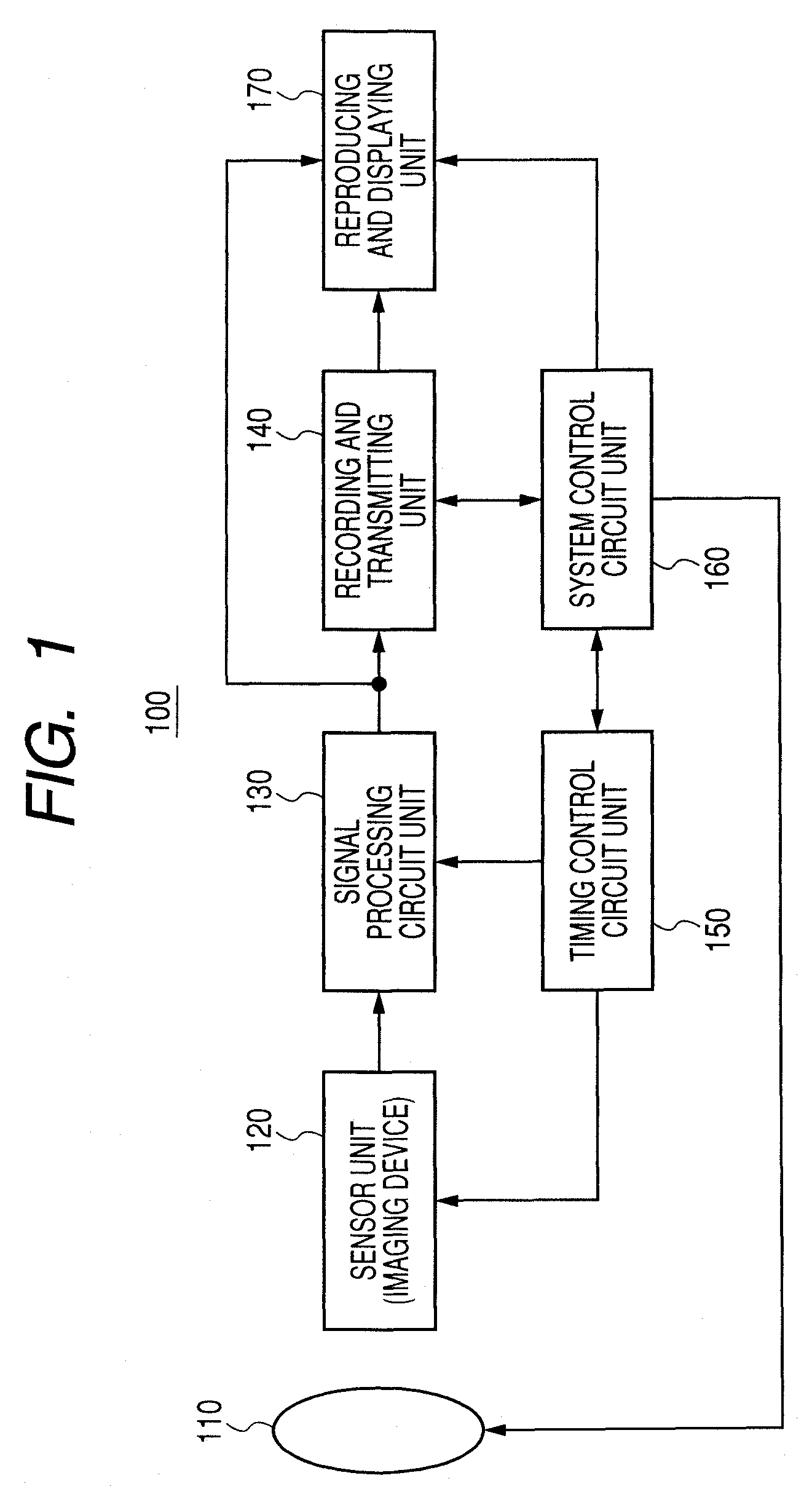
[0028]FIG. 1 is a diagram illustrating an example of a schematic configuration of an imaging device related to an embodiment of the present invention. An imaging device 100 comprises, for example, an optical unit 110, a sensor unit (imaging device) 120, a signal processing circuit unit 130, a recording and transmitting unit 140, a timing control circuit unit 150, a system control circuit unit 160 and a reproducing and displaying unit 170.

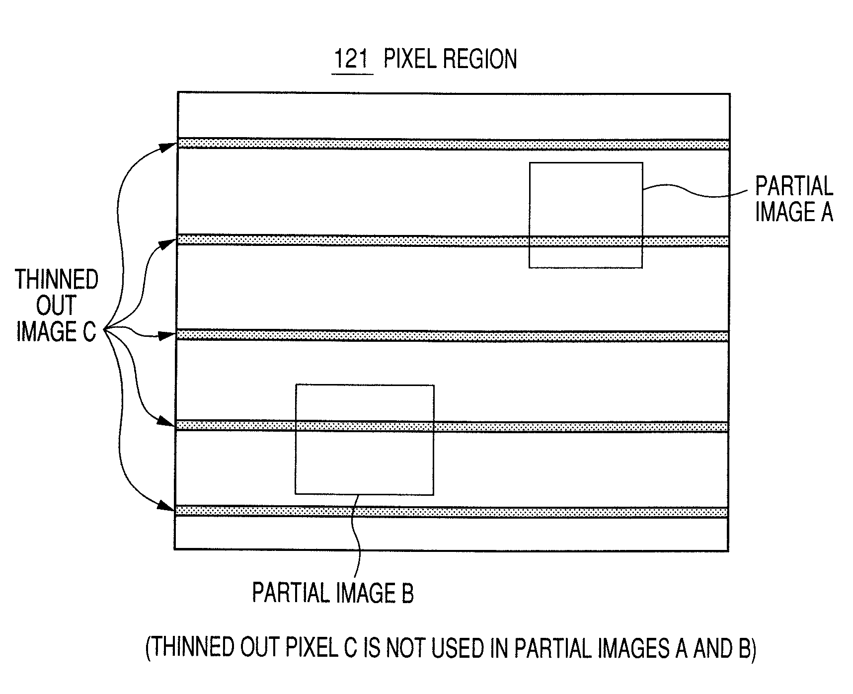
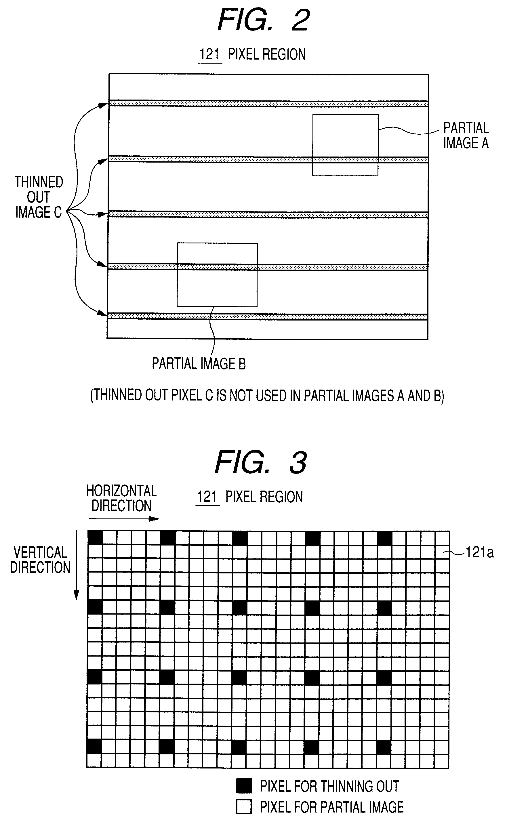
[0029]An incident light of an object through the optical unit 110 is focused on the sensor unit (imaging device) 120 to form an image. The sensor unit (imaging device) 120 includes, for example, a pixel region where pixel elements are arranged in a two dimensional matrix. When the incident light of an object is focused in the pixel region to form an image, the light of an object is converted into an electrical signal (image signal) by each...


PUM


Abstract

There is provided an imaging device which eliminates complexity in reading an image in low resolution and reading an image in high resolution and realizes prevention of decrease in frame rate. The device includes a pixel region including a plurality of pixel elements and imaging an incident light of an object as an image and a reading unit for thinning out a pixel element from the pixel region to read a thinned out image in low resolution and reading a partial image in resolution higher than the thinned out image from a partial region of the pixel region (a horizontal shift register and a vertical shift register), wherein the reading unit reads the thinned out image and the partial image from mutually different pixel elements and reads the thinned out image and the partial image as different imaging frames.

Description

BACKGROUND OF THE INVENTION[0001]1. Field of the Invention[0002]The present invention relates to an imaging device which includes a pixel region including a plurality of pixel elements and imaging an incident light of an object as an image and a driving method thereof.[0003]2. Description of the Related Art[0004]As a conventional imaging device capable of imaging a wide imaging area with low resolution and imaging a predetermined partial imaging area with high resolution, there is, for example, Japanese Patent Application Laid-Open No. H09-214836 and Japanese Patent Application Laid-Open No. 2000-032318.[0005]In Japanese Patent Application Laid-Open No. H09-214836, an imaging device capable of reading data of a predetermined pixel element is used. And a block mode for reading only the pixel element of a predetermined block among all pixel elements, and a skip mode for reading all pixel elements at a predetermined thinning-out rate are switched to drive, write in memory and display. ...

Claims


Application Information

Patent Timeline
Patent Type & Authority Patents(United States)
IPC IPC(8): H04N5/228H01L27/146H04N5/335H04N5/341H04N5/345H04N5/369H04N5/374
CPCH01L27/14603H04N3/155H04N5/3456H04N5/3454H04N5/37457H04N3/1562H04N25/42H04N25/445H04N25/443H04N25/533H04N25/778
Inventor OTA, KEISUKEHASHIMOTO, SEIJISHIGETA, KAZUYUKI
Owner CANON KK
Why Eureka
Try Eureka