Electronic communications system, apparatus and electrode layout method

a communication system and electrode layout technology, applied in the field of electromechanical communication techniques, can solve the problems of inability to maintain stable communication, weaken electrostatic coupling, and establish return paths, and achieve the effect of sufficient communication distances

Inactive Publication Date: 2010-12-28
NTT DOCOMO INC
View PDF18 Cites 110 Cited by
  • Summary
  • Abstract
  • Description
  • Claims
  • Application Information

AI Technical Summary

Benefits of technology

[0012]The present invention provides a solution for the above described problem. The present invention provides an electric field communications apparatus that can assure sufficiently great communication distances.
[0013]To solve the problem, the present invention provides an electric field communications system, which comprises a transmitter apparatus, comprising: a transmitter main electrode provided in a location so as to readily exert an electric effect on a dielectric; a transmitter return electrode; a signal generator that generates an electric signal; and a modulator that modulates a voltage difference between the transmitter main electrode and the receiver return electrode in response to the electric signal; a receiver apparatus, comprising: a receiver main electrode provided in a location where the receiver main electrode is readily subject to an electric effect from the dielectric; a receiver return electrode that establishes an electrostatic coupling with the transmitter return electrode; and a measuring part that measures electric status generated between the receiver main electrode and the receiver return electrode; wherein the measuring parts comprises: an electro-optical crystal that exhibits a Pockels Effect and modulates light penetrating the electro-optical crystal in response to an electric field in the space where the electro-optical crystal is located light emitting means that emits light to the electro-optical crystal; and light receiving means that receives light penetrating the electro-optical crystal, and output signals in response to the received light. According to the electric field communications system of the present invention, it is possible to increase the electro-static coupling of the transmitter apparatus and the receiver apparatus, and to use a high sensitivity electro-optical crystal.

Problems solved by technology

However, in communications based on the method, so-called PANs (Personal Area Networks), there has been the problem of establishing return paths.
Accordingly, when establishing the transmitting and receiving apparatus in a location that separates the transmitting and receiving apparatus from the ground, the electrostatic coupling weakens, and stable communications becomes impossible.
However, even technologies disclosed in the Patent documents cannot assure sufficiently long communication distances.
However, since this is for electrostatic coupling through the air, the distance between the return path of the transmitter apparatus and the receiver apparatus must not be overly increased.
In the case of performing electric field communications using the configurations disclosed in the Patent documents, it becomes impossible to communicate across a space as wide as the space between a person's head and pelvic region.
However, by using a configuration that combines the functions of cabinet and return path, it is not clear how an electric field reaching the receiver apparatus is specifically distributed in the interior of the apparatus.
For example, in a case that only a very small portion of the electric field reaches the part in which the electric field sensor is positioned, sensitivity to changes in the electric field cannot be improved.
In other words, using the technology disclosed in the patent documents, it is difficult to sufficiently raise the reception sensitivity because the electric field density at the location of the electric field sensor cannot be strictly estimated.

Method used


Image

  • Electronic communications system, apparatus and electrode layout method
  • Electronic communications system, apparatus and electrode layout method
  • Electronic communications system, apparatus and electrode layout method

Examples


first embodiment

A first embodiment will be described with reference to the drawings.

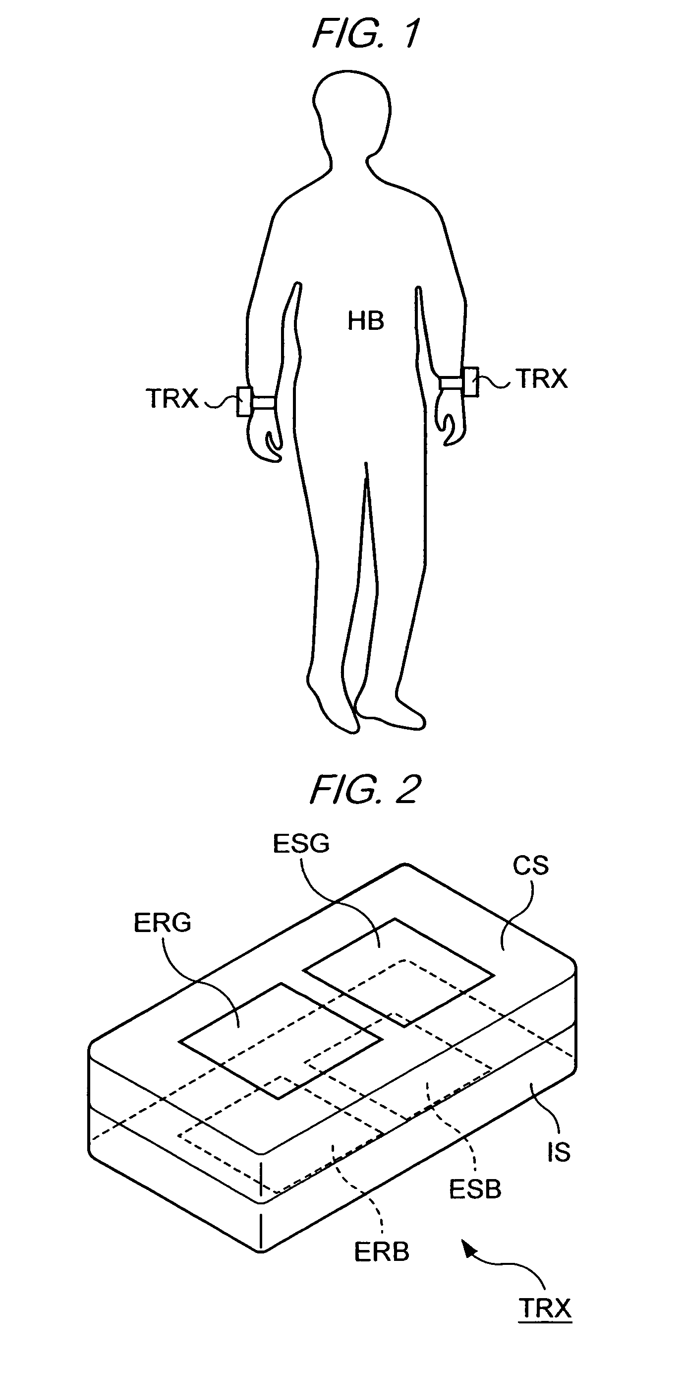
[0198]FIG. 1 shows an example of electric field communications apparatus TRX according to the present embodiment. As shown in FIG. 1, the electric field communications apparatus TRX is worn on human body HB. The electric field communications apparatus TRX can emit electric fields that vary in frequency from the tens of kHz to the multiples of MHz indicated for good conduction in the human body, and can detect electric fields that reach TRX through human body HB. Accordingly, several electric field communications apparatus TRX can perform communications through human body HB.

[0199]Electric field apparatus TRX can use a dielectric as a transmission medium, if the dielectric has conductivity through certain frequencies. Accordingly, electric field communications apparatus TRX can be placed in various locations, even outside the human body 1B, such as the walls, floors and ceilings of rooms. As well, electric field comm...

example 1

LAYOUT EXAMPLE 1

[0250]FIG. 15 schematically shows the communications for layout example 1.

[0251]In FIG. 15, an example of communications between electric field communications apparatus TRX1 and TRX2 is shown.

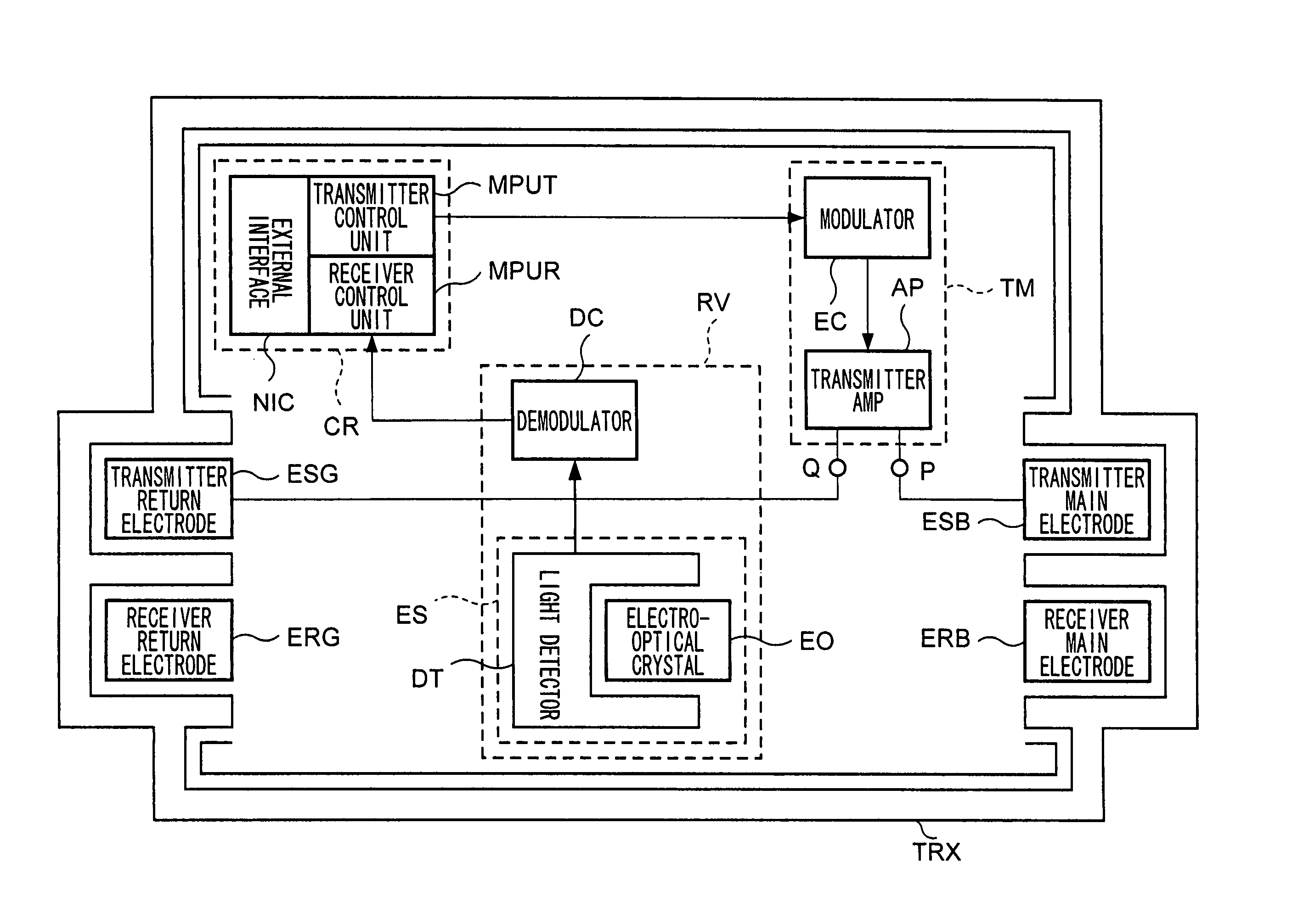
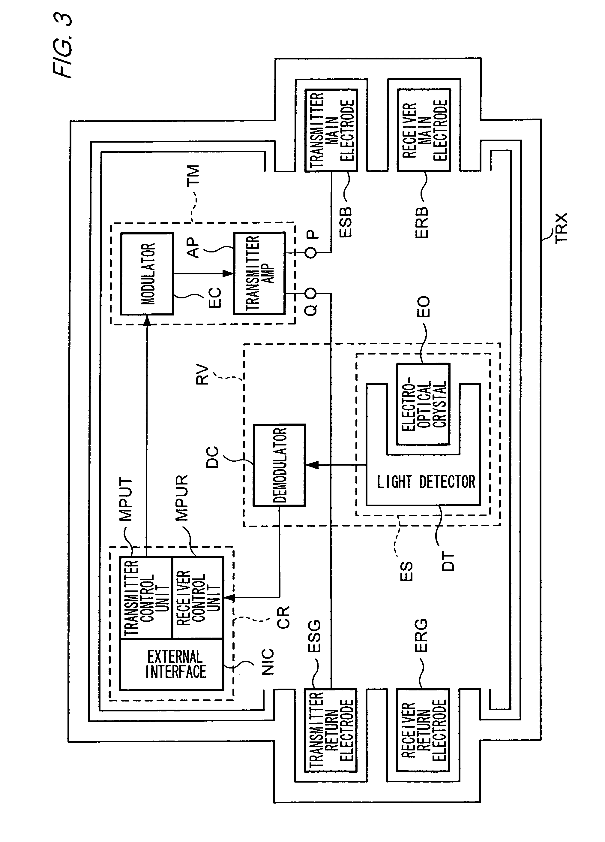
[0252]First, transmitter control unit MPUT2 of electric field communications apparatus TRX2 converts into transmission signals the data to be sent to electric field communications apparatus TRX1. Then, transmitter control unit MPUT2 outputs the transmission signals to modulator EC2. Modulator EC2 modulates the carrier waves in response to the transmission signals. Then, modulator EC2 outputs the modulated signal to transmitter amplifier AP2. Transmitter amplifier AP2 amplifies the modulated signal and converts it into the voltage difference between terminal P2 and terminal Q2. Then, an electric field is radiated from transmitter main electrode ESB2 based on the voltage difference. The electric field reaches through human body HB locations where electric field communications appa...

example 2

LAYOUT EXAMPLE 2

[0254]FIG. 16 schematically shows the communications for layout example 2. In FIG. 16, the communications between electric field communications apparatus TRX2a worn by user A and electric field communications apparatus TRX2b worn by user B, are illustrated.

[0255]First, the electric field modulated in response to the data to be transmitted is radiated from transmitter main electrode ERB2a of electric field communications apparatus TRX2a. For this situation, when the body of user A touches the body of user B, for example by a handshake, the electric field radiated in user A is transmitted to user B. Then, the electric field reaches electric field communications apparatus TRX2b. Then, electric field communications apparatus TRX2b acquires data sent by electric field communications apparatus TRX2a, and executes operations based on the data.

[0256]Moreover, concerning the operations of the process by which signals are radiated from electric field communications apparatus T...


PUM


Abstract

An electric field generated by another electric field communications apparatus reaches electric field sensor ES. Electric field sensor ES outputs an electric signal in response to the changes in the electric field. The electric field that reaches electric field sensor ES enters a return path of the electric field communications apparatus that is a source of the electric field. By locating electric field sensor ES between receiver main electrode ERB and receiver return electrode ERG, electric field intensity at the location where electric field sensor ES is positioned. Therefore, sensitivity of the changes in electric field for electric field communications apparatus TRX can be improved.

Description

BACKGROUND OF THE INVENTION[0001]1. Field of the Invention[0002]The present invention relates to techniques for communication using time-varying electric fields.[0003]2. Description of the Related Arts[0004]In recent years, methods have been proposed for performing communications using electrostatic fields induced in a dielectric such as the human body. This method was first disclosed in T. G. Zimmerman's paper “Personal Area Networks: Near-Field Intra-Body Communication” (IBM System Journal Vol. 35, No. 3&4, 1996-MIT Media Laboratory). According to this method, it is possible to implement a miniaturized device permitting a reduction in the electric power required of the device.[0005]However, in communications based on the method, so-called PANs (Personal Area Networks), there has been the problem of establishing return paths. As shown in FIG. 22, a PAN can use earth ground as a return path. For this reason, there is a need to establish an electrostatic coupling through the earth gr...

Claims


Application Information

Patent Timeline
Patent Type & Authority Patents(United States)
IPC IPC(8): H04B5/00H04B13/00
CPCH04B13/00
Inventor FUKUMOTO, MASAAKISUGIMURA, TOSHIAKINAKANO, HIROTAKA
Owner NTT DOCOMO INC
Why Eureka
Try Eureka