
Miniature circular mapping catheter

a miniature, sensor technology, applied in the direction of catheters, applications, therapy, etc., can solve the problems of limiting the placement of electrodes, the configuration of the transducer array and associated structures, and the difficulty of making the device collapse to a small diameter, etc., to achieve the formation of a ring-like lesion or the sensing of electrical potential at numerous locations

Inactive Publication Date: 2010-12-28
BOSTON SCI SCIMED INC
View PDF28 Cites 4 Cited by
  • Summary
  • Abstract
  • Description
  • Claims
  • Application Information

AI Technical Summary

Problems solved by technology

Providing electrical sensing structures on a balloon-like or other expansible ablation device complicates fabrication of the device and makes it more difficult to make the device collapse to a small diameter for advancing or withdrawing the device through the vascular system.
Further, mounting the electrodes on the same catheter as an ultrasonic transducer, as disclosed in the '484 patent, limits placement of the electrodes and the configuration of the transducer array and associated structures.
The particular structures shown in the '484 patent, for example, are not well suited to formation of a ring-like lesion or sensing of electrical potentials at numerous locations.
Use of a loop-forming sensing element entirely divorced from an ablation device, as contemplated in U.S. Pat. No. 6,628,976, necessarily requires separate steps for placement of such a device which adds both complexity and risk to the procedure.

Method used


Image

  • Miniature circular mapping catheter
  • Miniature circular mapping catheter
  • Miniature circular mapping catheter

Examples


second embodiment

[0030]A sensor probe in accordance with the invention has a composite body 200 (FIG. 5) including a tubular metallic shaft section 202 which may be formed from a stainless steel tube of the type commonly used to form hypodermic needles. Shaft section 202 defines an interior bore 203 (FIG. 6). Desirably, shaft section 202 has an outside diameter DS (FIG. 6) on the order of 1.25 mm or less, more desirably about 1 mm (0.040 inches) or less, and most preferably about 0.9 mm (0.035 inches). Preferably, shaft section 202 extends throughout the majority of the length of probe 200. For example, shaft section 202 may be on the order of 140 cm (55 inches) long.

[0031]A distal section 206 is mounted to the distal end 204 of shaft section 202. Distal section 206 includes a wire core 210 (FIG. 7) with a dielectric, biologically inert polymeric covering 212 overlying the core. The core desirably is formed from a metal such as a nickel-titanium alloy which can be formed to a preselected shape and w...

third embodiment

[0033]A sensor probe 300 in accordance with the invention is shown in FIG. 9. Sensor probe 300 has a proximal section 302 and a distal section 304. Proximal section 302 is approximately 90 percent of the length of sensor probe 300. Proximal section 302 includes a stainless steel hypotube coated with Teflon. The stainless steel hypotube provides pushability to the sensor probe 300 and transfers maximum force from a handle 306 to the opposite end of sensor probe 300. A core wire (not shown) runs through the proximal twelve inches of the hypotube to prevent it from collapsing during procedural manipulation. A plurality of electrodes (not shown) extend around a portion of a nitinol wire 312 (FIG. 10) that forms a loop 324 (FIG. 11). The electrodes are electrically insulated from nitinol wire 312. One example of a manner in which the electrodes may be insulated from nitinol wire 312 may be seen in FIG. 3 where the nitinol wire is designated by numeral 94. As seen in FIG. 3 insulated wire...


PUM


Abstract

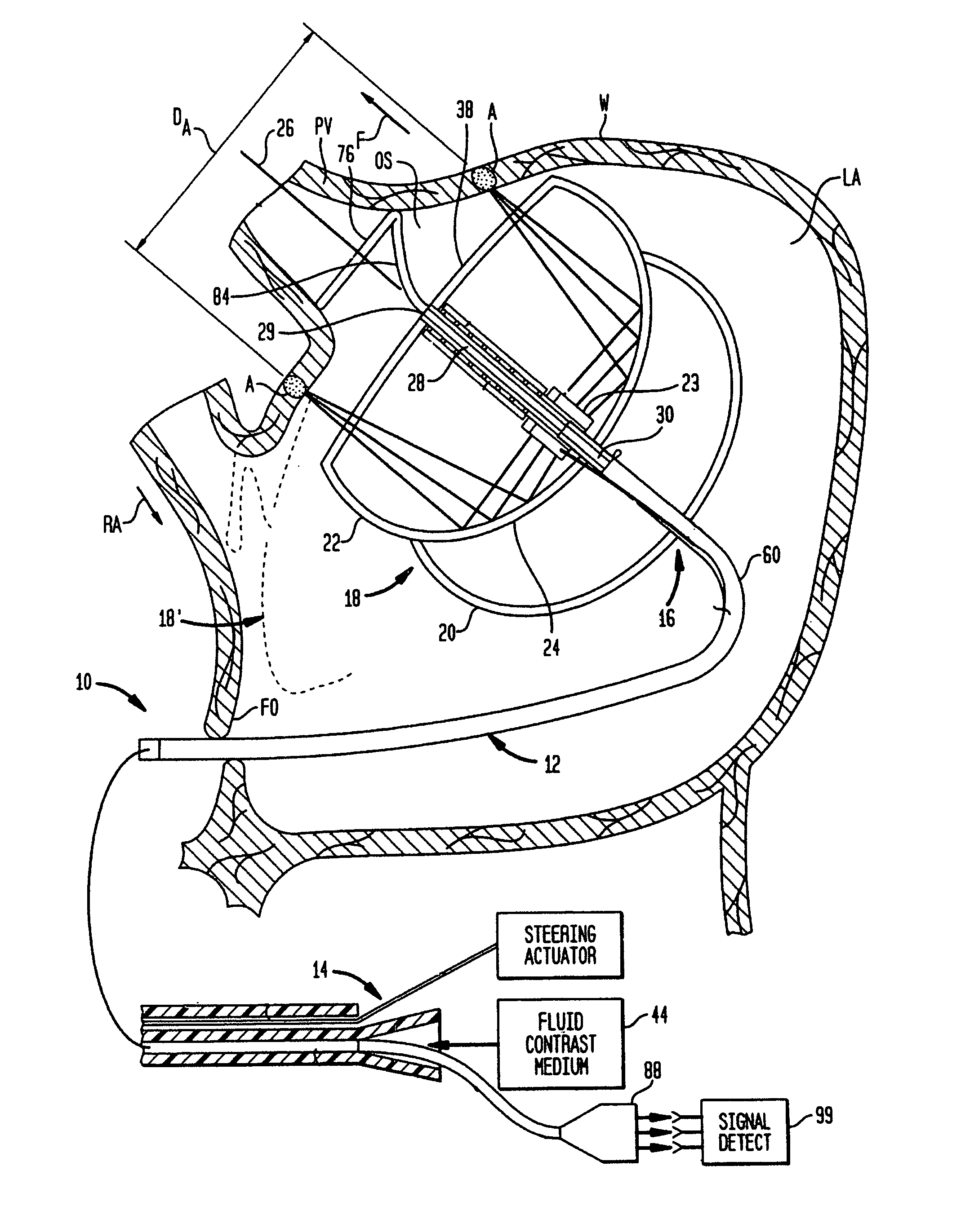
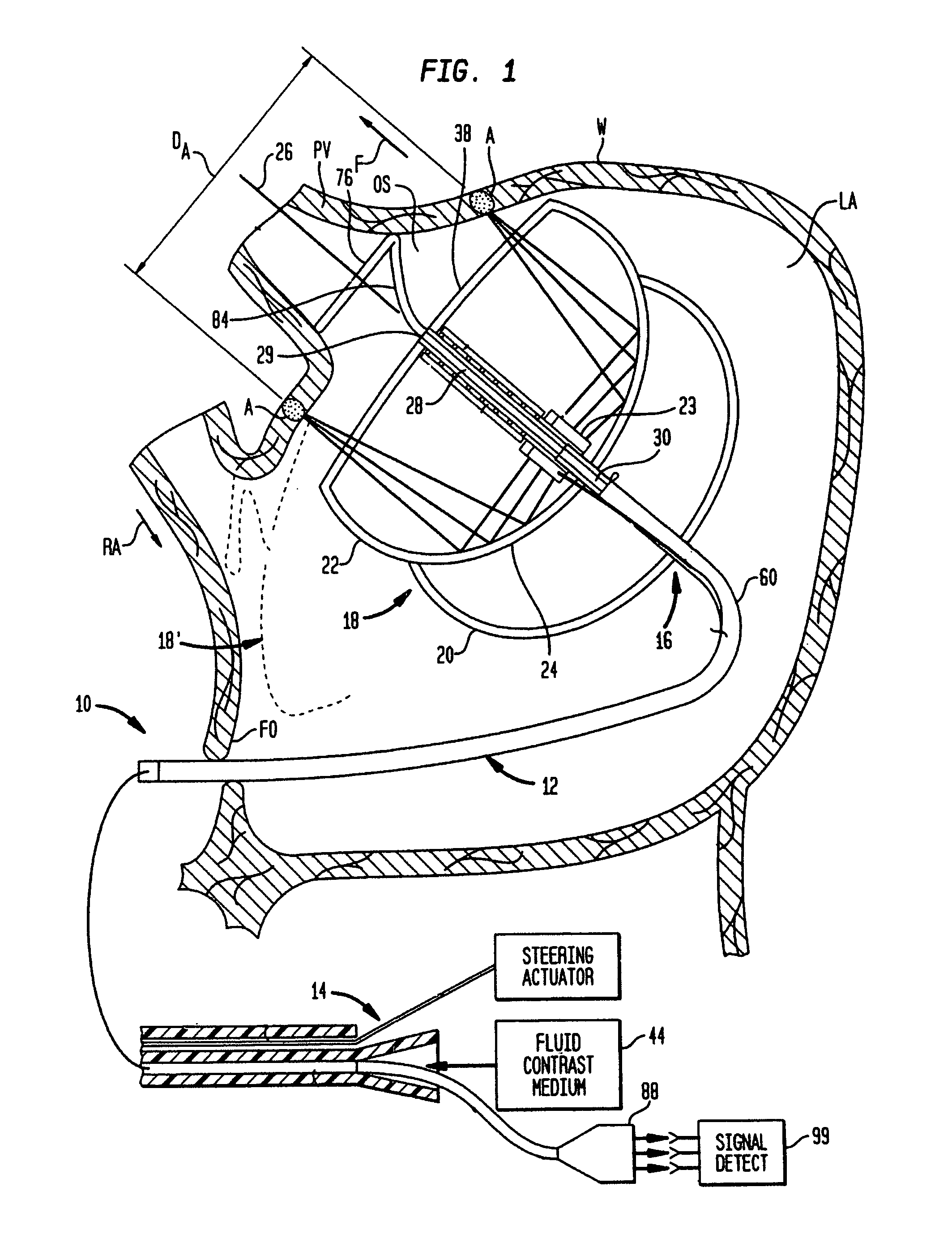
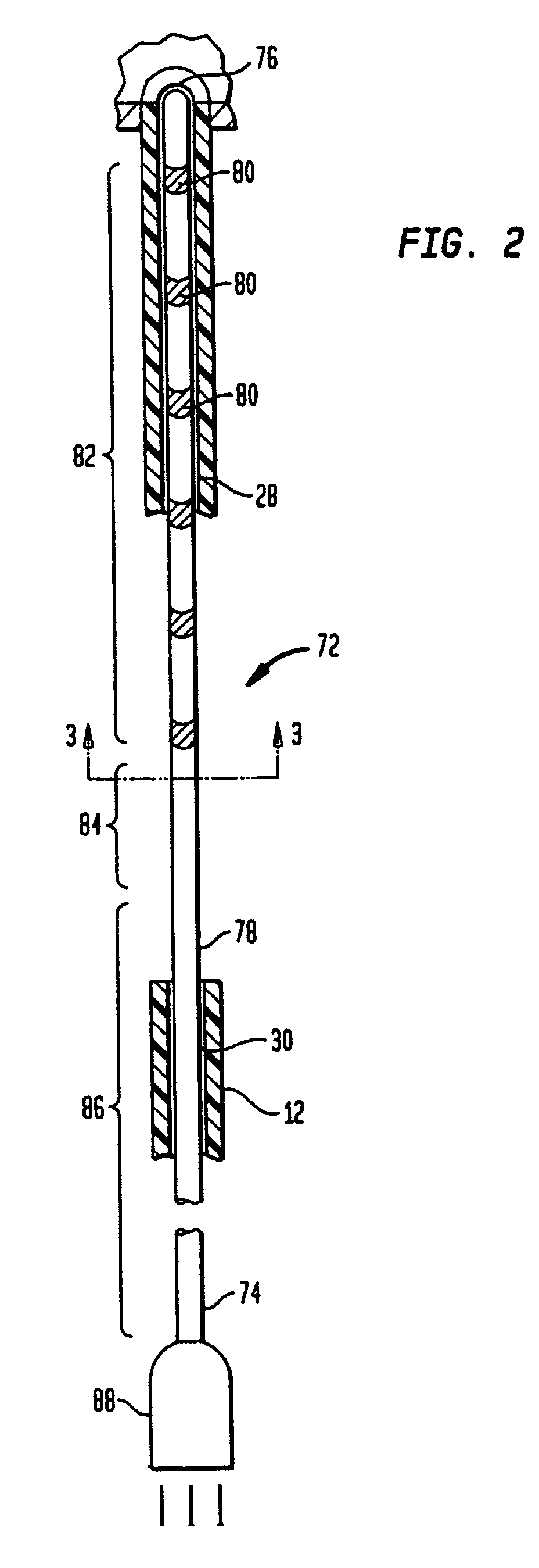
A cardiac ablation device, including a catheter and an expandable ablation element incorporating one or more balloons at the distal end of the catheter, has a continuous passageway extending through it from the proximal end of the catheter to the distal side of the expandable ablation element. A probe carrying electrodes is introduced through this passageway and deploys, under the influence of its own resilience, to a structure incorporating a loop which is automatically aligned with the axis of the expandable ablation device, so that minimal manipulation is required to place the probe. The probe may have an atraumatic tip with a ball formed at the leading edge. The atraumatic tip prevents any tissue damage such as perforation of heart wall.

Description

BACKGROUND ART[0001]The present invention relates to apparatus and methods for cardiac ablation and to miniature sensor structures useful in such apparatus and methods.[0002]Contraction or “beating” of the heart is controlled by electrical impulses generated at nodes within the heart and transmitted along conductive pathways extending within the wall of the heart. Certain diseases of the heart known as cardiac arrhythmias involve abnormal generation or conduction of the electrical impulses. One such arrhythmia is atrial fibrillation or “AF.” Certain cardiac arrhythmias can be treated by deliberately damaging the tissue along a path crossing a route of abnormal conduction, either by surgically cutting the tissue or by applying energy or chemicals to the tissue, so as to form a scar. The scar blocks the abnormal conduction. For example, in treatment of AF, it has been proposed to ablate tissue in a partial or complete loop around a pulmonary vein, within the ostium or opening connecti...

Claims


Application Information

Patent Timeline
Patent Type & Authority Patents(United States)
IPC IPC(8): A61N1/00
CPCA61B5/0422A61B5/6851A61B5/6856A61B5/6857A61B18/1492A61B18/02A61B2017/00053A61B2017/22038A61B2018/00214A61B2018/00351A61B2018/00357A61B2018/144A61N7/022A61B5/287
Inventor JUNG, EUGENE J.SHIN, DONG IKVAUGHAN, ERIC SCOTT
Owner BOSTON SCI SCIMED INC
Learn More