Dispersing apparatus, ceramic slurry preparation method, and monolithic ceramic electronic component and manufacturing method thereof

a technology of monolithic ceramic and electronic components, which is applied in the direction of flow mixers, capacitor manufacture, chemical/physical processes, etc., can solve the problems of ineffective dispersion of agglomerated particles, inability to substantially improve the dispersion method, and inability to efficiently manufacture monolithic ceramic electronic components. , to achieve the effect of efficient manufacturing of monolithic ceramic electronic components, efficient production of highly reliable ceramic electronic components, and increased capacity

Active Publication Date: 2011-01-04
MURATA MFG CO LTD
View PDF17 Cites 0 Cited by
  • Summary
  • Abstract
  • Description
  • Claims
  • Application Information

AI Technical Summary

Benefits of technology

[0014]a dispersing apparatus that can efficiently disperse agglomerated particles in a slurry at a lower energy than ever and that can reliably prepare fine and uniform particles or a slurry containing such particles,
[0066]The monolithic ceramic electronic component described hereinabove is manufactured by the disclosed monolithic ceramic electronic component manufacturing method, and includes a ceramic element using ceramic green sheets having few defects. Accordingly, the monolithic ceramic electronic component can be highly reliable and have, for example, no interlayer short-circuiting.

Problems solved by technology

However, the impact force as a dispersing stress has a broad distribution and occurs dispersedly in a wide range; hence, a high dispersing stress is difficult to produce.
However, the energy of the shearing stress is used for rotating the agglomerated particles, and consequently it is inefficient in dispersing (including crushing and grinding) the agglomerated particles even though it is more efficient than the dispersing stress in the foregoing Patent Document 1 (in which impact force is used as the main dispersing stress).
Although cavitation may also be applied for dispersal, this technique does not substantially improve upon the dispersing method using impact force or shearing stress.
On the contrary, an excessively long second channel may increase the pressure loss.
An excessively short second channel may seriously wear out.

Method used


Image

  • Dispersing apparatus, ceramic slurry preparation method, and monolithic ceramic electronic component and manufacturing method thereof
  • Dispersing apparatus, ceramic slurry preparation method, and monolithic ceramic electronic component and manufacturing method thereof
  • Dispersing apparatus, ceramic slurry preparation method, and monolithic ceramic electronic component and manufacturing method thereof

Examples


example 1

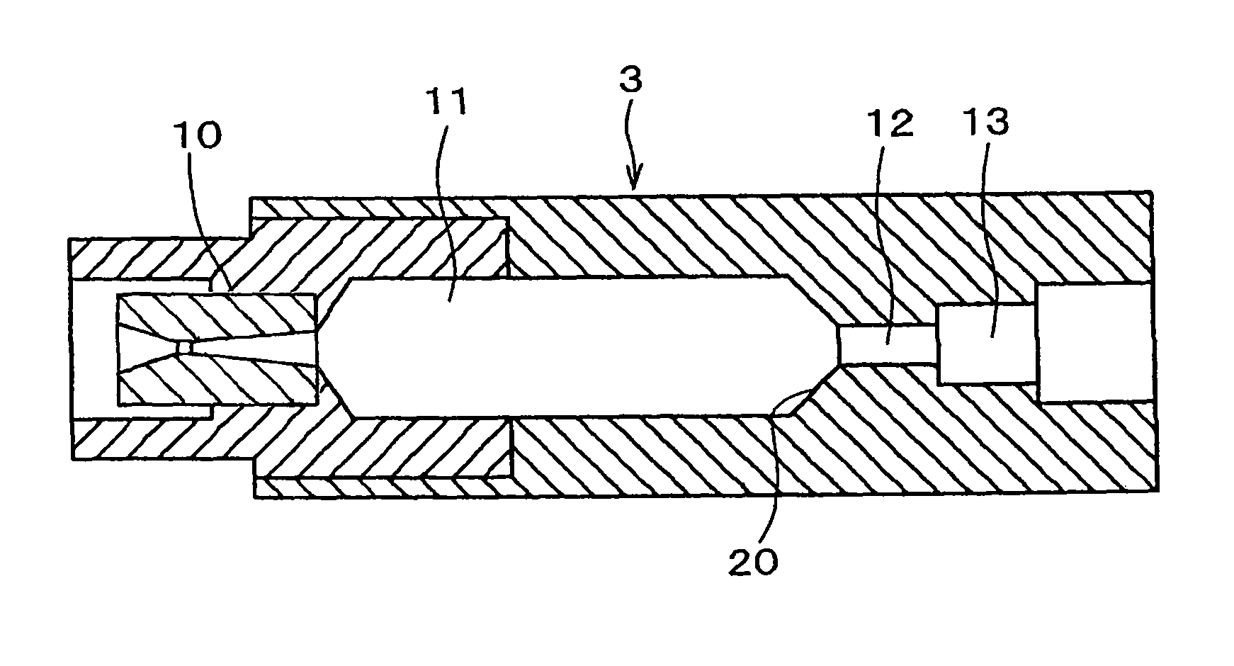
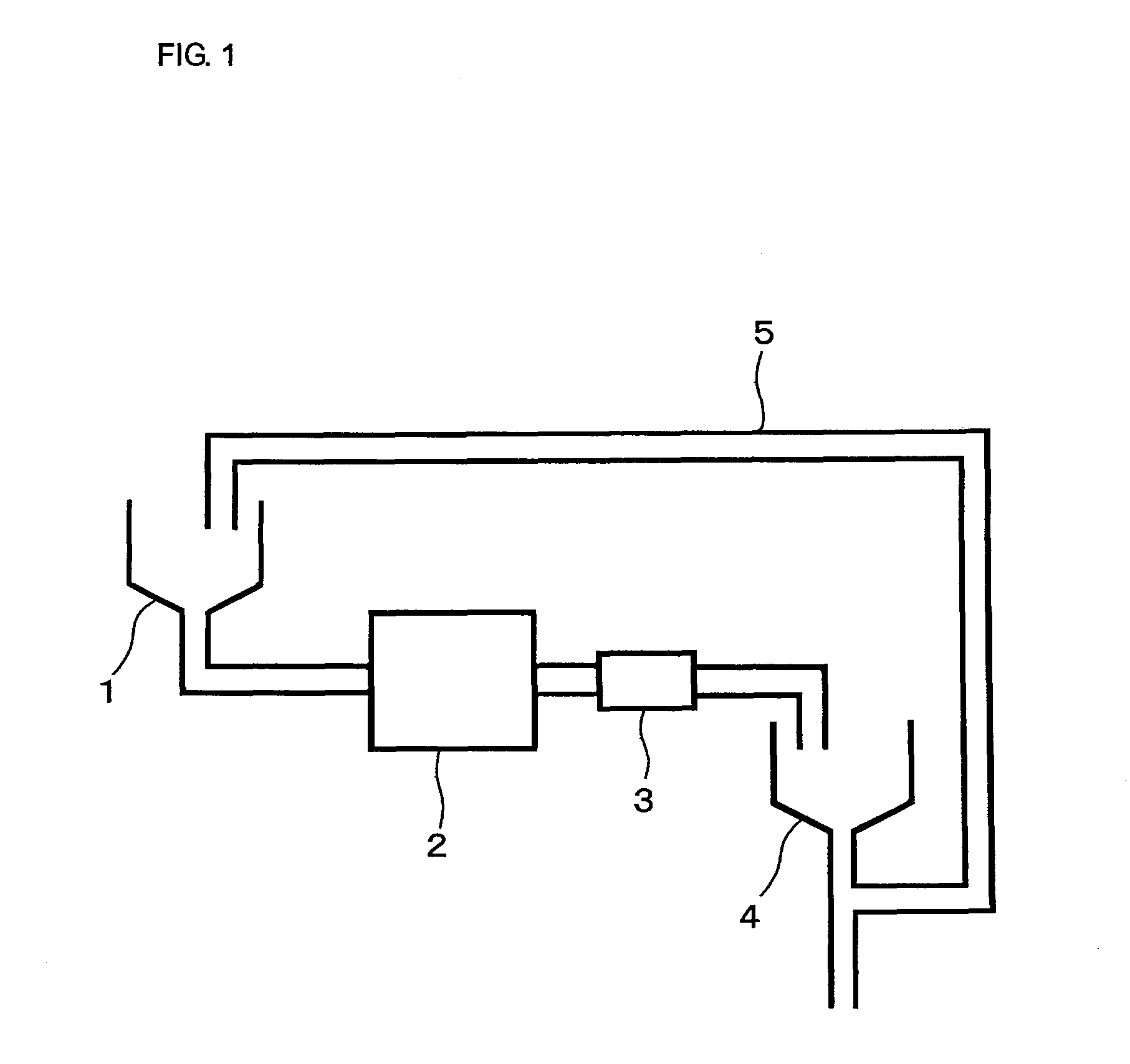
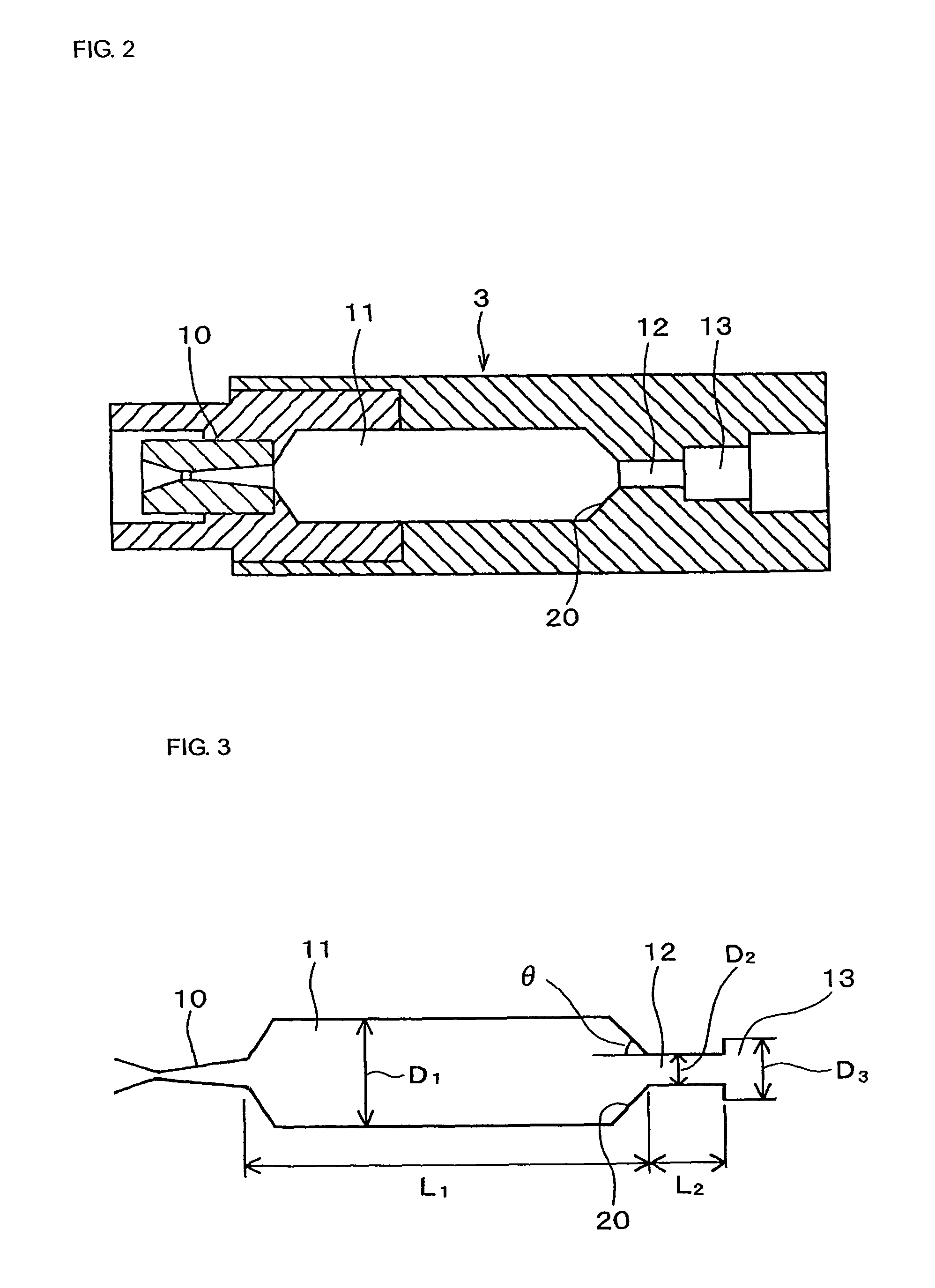
[0075]FIG. 1 is a schematic diagram of an example of the structure of a dispersing apparatus. FIG. 2 is a sectional view of the structure of a dispersing section of the dispersing apparatus according to the example; FIG. 3 is a diagram showing the dimensions and angles of the dispersing section of the dispersing apparatus according to the example; and FIG. 4 is a sectional view of a nozzle of the dispersing section of the dispersing apparatus according to the example.

[0076]As shown in FIG. 1, the dispersing apparatus of the present example includes a feed tank 1 into which a ceramic slurry containing agglomerated ceramic particles is fed, a pressurizing section 2 in which a pressure is applied to the slurry containing the agglomerated ceramic particles, a dispersing section 3 through which the ceramic slurry pressurized in the pressurizing section 2 is passed to disperse the agglomerated ceramic particles, and a discharge tank 4 through which the dispersed ceramic slurry is discharg...

example 2

[0129]In Example 2, a dispersing apparatus satisfying the following requirements was prepared. For example, in this example, the first channel may have a length L1 satisfying the relationship (1): {10×(4Sn / π)1 / 2}≦L1≦(100×(4Sn / π)1 / 2} (1), wherein Sn represents the cross section in the direction perpendicular to the jet stream of the straight portion of the nozzle; and / or the first channel may have a larger cross section S1 in the direction perpendicular to the jet stream than the cross section S2 of the second channel in the direction perpendicular to the jet stream, and the cross section S1 is 400 times or less the cross section Sn of the straight portion of the nozzle in the direction perpendicular to the jet stream.

[0130]The dispersing apparatus of Example 2 essentially has the same structure as the dispersing apparatus of Example 1 shown in FIGS. 1, 2, and 3.

[0131]Parts of the dispersing apparatus each have the following dimensions and conditions (see FIGS. 3 and 4).

[0132](1) Fir...


PUM

PropertyMeasurementUnit
tapered angleaaaaaaaaaa
mean particle sizeaaaaaaaaaa

Abstract

A dispersing apparatus that can efficiently disperse agglomerated particles in a slurry at a lower energy, a method for preparing a ceramic slurry containing ceramic particles that have been dispersed with the dispersing apparatus, a reliable monolithic ceramic electronic component manufactured using ceramic green sheets formed of the ceramic slurry, and a method for manufacturing the monolithic ceramic electronic component. A slurry containing agglomerated particles is passed through a dispersing section to produce a tensile stress, and the tensile stress is applied to the agglomerated particles in the slurry, thereby dispersing the agglomerated particles. The dispersing section includes a nozzle, a first channel thorough which a jet generated through the nozzle passes, and a cylindrical second channel through which the jet coming through the first channel passes to produce a tensile stress. The nozzle, the first channel, and the second channel are disposed in that order from the upstream side to the downstream side.

Description

CROSS-REFERENCE TO RELATED APPLICATIONS[0001]This is a continuation under 35 U.S.C. §111 (a) of PCT / JP2006 / 301691 filed Feb. 1, 2006, and claims priority of JP2005-71745 filed Mar. 14, 2005 and JP2005-172843 filed Jun. 13, 2005, incorporated by reference.BACKGROUND[0002]1. Technical Field[0003]The present disclosure relates to a dispersing apparatus for dispersing agglomerated particles in a slurry, a method for preparing a ceramic slurry containing ceramic particles that have been dispersed by the dispersing apparatus, a method for manufacturing a monolithic ceramic electronic component using ceramic green sheets formed of the ceramic slurry, and a monolithic ceramic electronic component manufactured by the method.[0004]2. Background Art[0005]In a known method for dispersal and emulsification, for preparing a ceramic slurry, a ceramic liquid containing an organic solvent or water and ceramic powder having a mean particle size in the range of 0.01 to 3 μm is dispersed under a high p...

Claims


Application Information

Patent Timeline
Patent Type & Authority Patents(United States)
IPC IPC(8): B05B1/00C04B35/00
CPCB01F3/12B01F5/0682B01F5/0689B28C5/06C04B35/4682C04B35/62635C04B35/6264H01C7/18H01G4/12H01G13/00C04B2235/5445C04B2235/77C04B2235/963H01G4/30Y02P40/60B01F23/50B01F25/45B01F25/45211C04B35/622B02C19/06B28C1/04
Inventor NAKA, KAZUYUKITASHIMA, TAKESHI
Owner MURATA MFG CO LTD
Why Eureka
Try Eureka