
Waste water treatment system with buffering device and waste water treatment method therefor

a waste water treatment system and waste water treatment technology, applied in the direction of water treatment parameter control, specific water treatment objectives, treatment control/steering, etc., can solve the problems of reducing the efficiency of whole waste water treatment system, reducing energy consumption, and reducing energy consumption. , to achieve the effect of reducing the production of large salt, reducing the running time proportion, and slowing down the plugging

Active Publication Date: 2020-09-08
AQUACELL INC
View PDF9 Cites 0 Cited by
  • Summary
  • Abstract
  • Description
  • Claims
  • Application Information

AI Technical Summary

Benefits of technology

The present invention is a device that reduces the production of large salts and walling in the circulation crystallizer, slows down the plugging, and improves the operating efficiency of the device. The method of the present invention reduces the running time proportion of high-concentration waste water, reduces the plugging of the pipe, and improves the quality of the treated water. The method also reduces energy consumption and improves the crystallization effect.

Problems solved by technology

Among them, it is difficult to precisely define the residence time of the crystal in the crystallizer because the particle size of the crystallizer is not uniform and unstable.
In addition, due to the formation of large salt in the crystallizer, plugging often occurs in actual operation, and plugging causes the entire waste water treatment system to have a lower treatment efficiency and higher energy consumption, which is not conducive to energy conservation and emission reduction.

Method used


Image

  • Waste water treatment system with buffering device and waste water treatment method therefor

Examples


embodiments

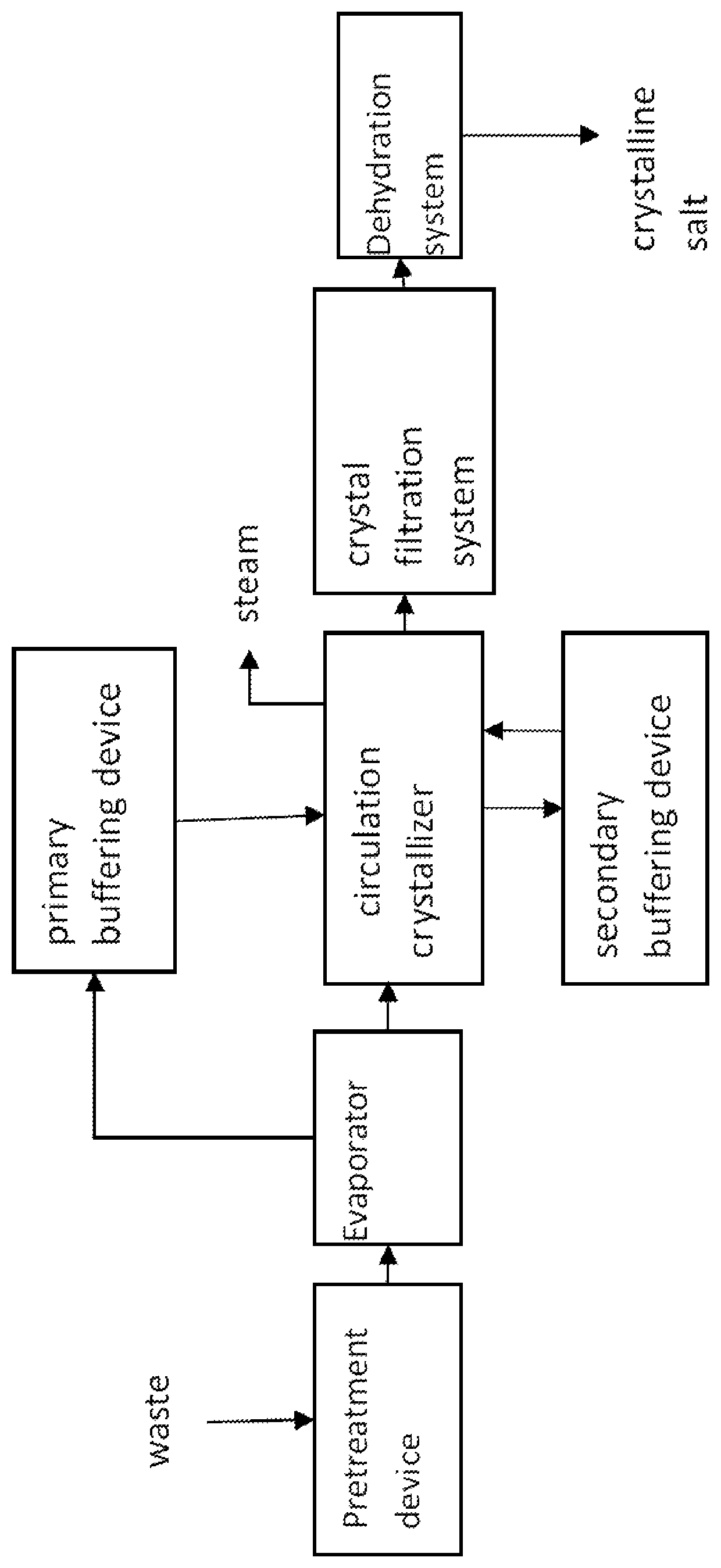
[0026]With reference to the FIGURE, the waste water treatment system with a buffering device of the present embodiment comprises a waste water pretreatment device, an evaporator, a circulation crystallizer, a crystal filtration device, a dehydration device, a primary buffering device and a secondary buffering device; the waste water pretreatment device, the evaporator, the circulation crystallizer, the crystal filtration device, the dehydration device are sequentially communicated; one end of the primary buffering device is in bidirectional communication with the circulation crystallizer and the other end is connected with the evaporator; the secondary buffering device is in bidirectional communication with the circulation crystallizer; both the primary buffering device and the secondary buffering device include a plurality of buffers, of which each is provided with a detection element related to the liquid level, and the circulation crystallizer is provided with a detection element...

embodiment 2

[0033]The waste water treatment method for the waste water treatment system with a buffering device of the present embodiment comprises the steps of:

[0034]S1, starting the waste water treatment system other than the primary buffering device and the secondary buffering device and entering S2 when entering the stable evaporation stage;

[0035]S2, in the crystallization process of the circulating crystallizer, existing one or more of the following operating conditions:

[0036]operating conditions 1: when the characteristic value of the solution in the circulation crystallizer >a predetermined threshold K, the liquid in the primary buffering device is controlled to flow to the circulation crystallizer;

[0037]operating conditions 2: when the characteristic value of the solution in the circulation crystallizer

[0038]operating conditions 3: when the characteristic value...

PUM

PropertyMeasurementUnit
pressureaaaaaaaaaa
conductivityaaaaaaaaaa

Abstract

Disclosed is a waste water treatment system with a buffering device, the system comprising a waste water pretreatment device, an evaporator, a circulating crystallizer, a crystal filtration device and a water removal device which communicate with each other in sequence, and further comprising a primary buffering device and a secondary buffering device, wherein one end of the primary buffering device is in bi-directional communication with the circulating crystallizer, and the other end thereof is connected to the evaporator; and the secondary buffering device is in bi-directional communication with the circulating crystallizer. Further disclosed is a waste water treatment method for a waste water treatment system with a buffering device.

Description

FIELD OF THE APPLICATION[0001]The present invention relates to the field of waste water treatment, in particular, to a waste water treatment system with a buffering device and a waste water treatment method therefor.BACKGROUND OF THE APPLICATION[0002]At present, general-purpose waste water treatment systems include pretreatment subsystems, falling film evaporators, forced circulation crystallizers, crystal filtration subsystems, and centrifugal dehydration subsystems. Among them, it is difficult to precisely define the residence time of the crystal in the crystallizer because the particle size of the crystallizer is not uniform and unstable. In addition, due to the formation of large salt in the crystallizer, plugging often occurs in actual operation, and plugging causes the entire waste water treatment system to have a lower treatment efficiency and higher energy consumption, which is not conducive to energy conservation and emission reduction.SUMMARY OF THE APPLICATION[0003]The pu...

Claims


Application Information

Patent Timeline
Patent Type & Authority Patents(United States)
IPC IPC(8): C02F1/04C02F1/00C02F1/52
CPCC02F1/52C02F1/048C02F1/008C02F2209/05C02F2301/046C02F2209/06C02F2209/02C02F2209/001C02F2209/11C02F2209/42C02F2001/5218C02F2209/01C02F1/043C02F2303/22
Inventor TIAN, XUFENG
Owner AQUACELL INC
Learn More