Supersonic aircraft footprint spreading control system and method

a control system and supersonic technology, applied in the direction of airflow influencers, fuselages, transportation and packaging, etc., can solve the problems of pressure footprint, supersonic wave drag, sonic boom, etc., and achieve the effect of reducing sonic boom and reducing sonic boom

Inactive Publication Date: 2011-01-04
VEHICLE RES
View PDF64 Cites 6 Cited by
  • Summary
  • Abstract
  • Description
  • Claims
  • Application Information

AI Technical Summary

Benefits of technology

[0003]The present invention in an exemplary embodiment optimizes the process of spreading the weight of a supersonic aircraft downstream over a larger area to reduce the pressure intensity on the ground and to reduce the peak pressures of the lead and the aft shock waves. This sonic boom reduction is initiated by sequencing the several elements of wing lift to minimize shock wave strength and thereby reduce supersonic wave drag. This process replaces the forward under wing shock wave by an array of weak compression waves. A portion of the aircraft propulsion compressor air is relocated below the wing as a planar higher mach number jet to generate a vortex array shield to intercept and reflect these weak waves upward to pressurize the aft undersurface of the wing. The higher Mach number underwing jet also provides a higher velocity along this wing undersurface. The underwing flow, energized in this manner, will form a vortex array between the jet stream and the ambient air flow which intercepts the lead shock wave, in the form of compression waves, and reflects them toward the aft undersurface of the wing, causing a reduced residual of the waves to pass through to the ground and make a much reduced pressure rise for an inaudible sonic boom. Such flow will assume a direction approaching that of the horizontal flow above the wing, reducing the strength of the closing shock wave required to align these flows. The resulting closing shock is weaker and shallower because the intersecting streams now intersect at a smaller angle, requiring a weaker shock wave to align them. The resulting shock wave, which is nearly completely dissipated, will spread a ground pressure footprint downstream, substantially reducing the supersonic wave drag and the sonic boom. One or more pressure sensors, located on the aft wing undersurface, and an aircraft velocity sensor control the position, mass flow, velocity, and inclination of the underwing jet of engine compressor air.
[0004]In another exemplary embodiment, a system is provided whereby the forward and aft shock waves are modified as a function of velocity, and / or temperature and / or pressure minimizing their strength resulting in the spreading of the aircraft footprint far down stream, thereby reducing the footprint intensity and the sonic boom created, consequently forming a shock-free system. In an exemplary embodiment, the system adjusts an under-wing planar jet flow as a function of ambient air flow velocity, and / or temperature and / or pressure so as to minimize the sonic boom created during supersonic flight.
[0008]In yet a further exemplary embodiment, a method for reducing a sonic boom generated when an aircraft flies from transonic to supersonic speeds is provided. The method includes generating a jet flow below a wing for energizing a free stream flow across an undersurface of the wing, and controlling the mass flow rate of the jet flow, the velocity of the jet flow and the direction of the jet flow to reflect compression waves generated by the aircraft wing upward in a diverging array for pressurizing an aft undersurface of said wing while at transonic speeds and while at supersonic speeds. In another exemplary embodiment, the mass flow rate is varied in response to variations in free stream airflow and pressure and the jet flow velocity is varied in response to a velocity of the wing for maintaining the difference between the velocity of the jet flow and the velocity of the free stream airflow to a level not greater than Mach 2.
[0009]In yet another exemplary embodiment, a method for reducing a sonic boom generated when an aircraft having a wing flies from transonic to supersonic speeds is provided. The method includes generating an aft wing shock wave, generating an aircraft pressure footprint, weakening the aft shock wave and extending the footprint at least 10 miles downstream from the wing. In a further exemplary embodiment, the method includes extending the shock wave at least 10 miles downstream from the wing upon generation of the shock wave. In another exemplary embodiment, extending the footprint includes aligning an air flow across an under surface of the wing with an airflow across an upper surface of the wing. In yet a further exemplary embodiment, extending the footprint includes modifying the aft shock wave and a forward shock wave.

Problems solved by technology

The resulting shock wave, which is nearly completely dissipated, will spread a ground pressure footprint downstream, substantially reducing the supersonic wave drag and the sonic boom.

Method used


Image

  • Supersonic aircraft footprint spreading control system and method
  • Supersonic aircraft footprint spreading control system and method
  • Supersonic aircraft footprint spreading control system and method

Examples


Embodiment Construction

[0017]In the following paragraphs like numbers refer to the same or similar items from figure to figure.

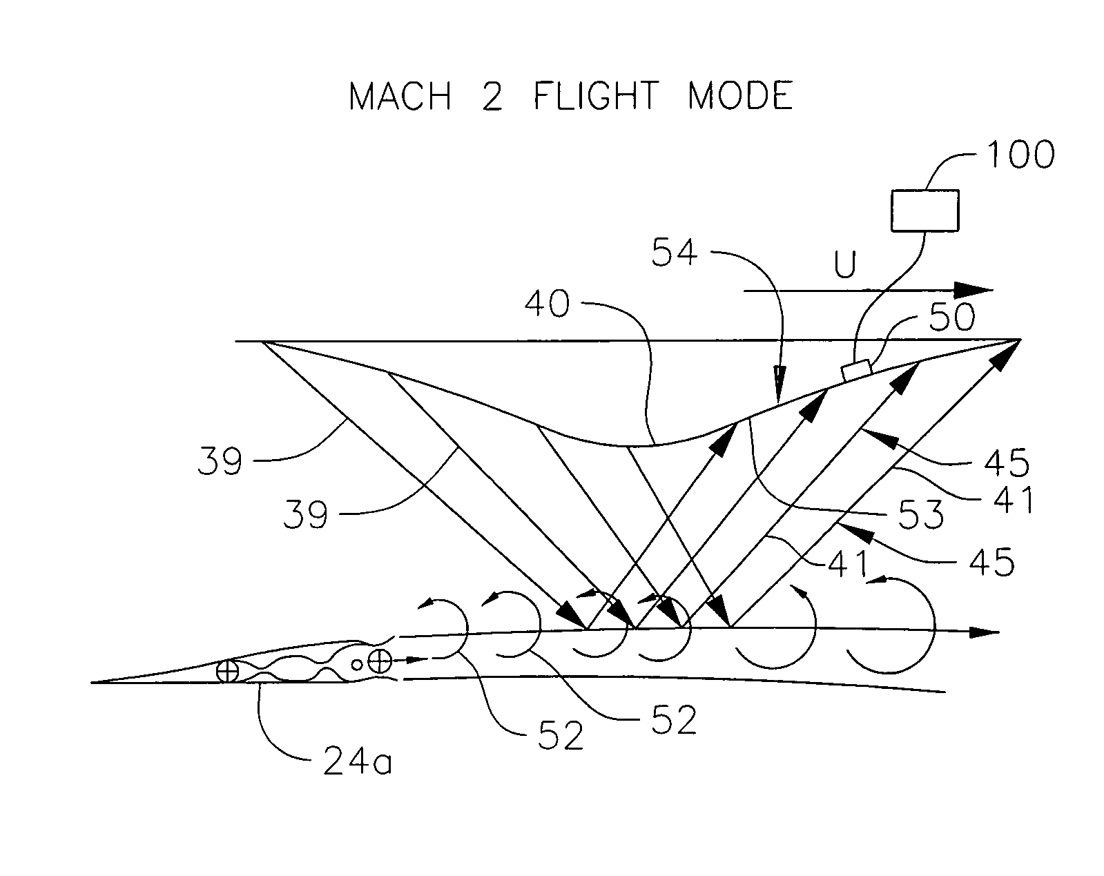
[0018]The weight of an airplane in flight appears on the ground as a force which may be expressed as the product of a footprint pressure times the area over which it acts. For a subsonic aircraft this footprint area is very large, in the form of a circular mound, with a pressure so weak that it cannot be felt on the ground and a pressure rise so small that no audible sonic boom is heard. For a conventional supersonic aircraft, in contrast, the pressure footprint area is very small, in the form of an “N” wave 20, and the corresponding pressure rise is rapid and strong, producing a very annoying sonic boom (FIG. 3A).

[0019]The footprint is small because shock waves bound the footprint area and these waves both closely approach the same Mach line from opposing sides. Applicant has discovered that a larger footprint would have a corresponding initial and closing pressure rise and sonic...


PUM


Abstract

A method and system to optimize the process a spreading the weight of supersonic aircraft downstream over a large area to reduce the pressure and intensity on the ground as function of air flow velocity, temperature, and / or pressure is provided.

Description

CROSS-REFERENCE TO RELATED APPLICATIONS[0001]This application is based upon and claims priority on U.S. Provisional Application No. 60 / 673,747, filed on Apr. 21, 2005 and U.S. Provisional Application No. 60 / 672,465, filed on Apr. 18, 2005, the contents of both of which are incorporated herein by reference.BACKGROUND OF THE INVENTION[0002]Currently known shock reducing systems which reduce the generation of shock waves and thereby the sonic boom during supersonic flight are designed for optimum performance at a given flight speed. However, as the flight speed varies, as for example, between transonic flight mode to various other supersonic modes, the effectiveness of the system to reduce shock wave and thus sonic boom is reduced. Consequently, a system that provides for optimized reduction or alleviation of shock waves and thus reduction or alleviation of sonic boom is desired.SUMMARY OF THE INVENTION[0003]The present invention in an exemplary embodiment optimizes the process of spre...

Claims


Application Information

Patent Timeline
Patent Type & Authority Patents(United States)
IPC IPC(8): B64C23/06B64C1/40
CPCB64C23/04B64C30/00
Inventor RETHORST, SCOTT
Owner VEHICLE RES
Why Eureka
Try Eureka