Eureka AIR delivers breakthrough ideas for toughest innovation challenges, trusted by R&D personnel around the world.

Exhaust gas purifying catalyst and exhaust gas purifying method

a technology of exhaust gas purification catalyst and purification method, which is applied in the direction of physical/chemical process catalysts, arsenic compounds, separation processes, etc., can solve the problem of insufficiency of conversion efficiency of composite oxides for exhaust gas emissions, and achieve the effect of facilitating nox reduction reaction, improving oxygen storage/release capability, and poor nox reduction function

Inactive Publication Date: 2011-01-04
MAZDA MOTOR CORP
View PDF19 Cites 5 Cited by
  • Summary
  • Abstract
  • Description
  • Claims
  • Application Information

AI Technical Summary

Benefits of technology

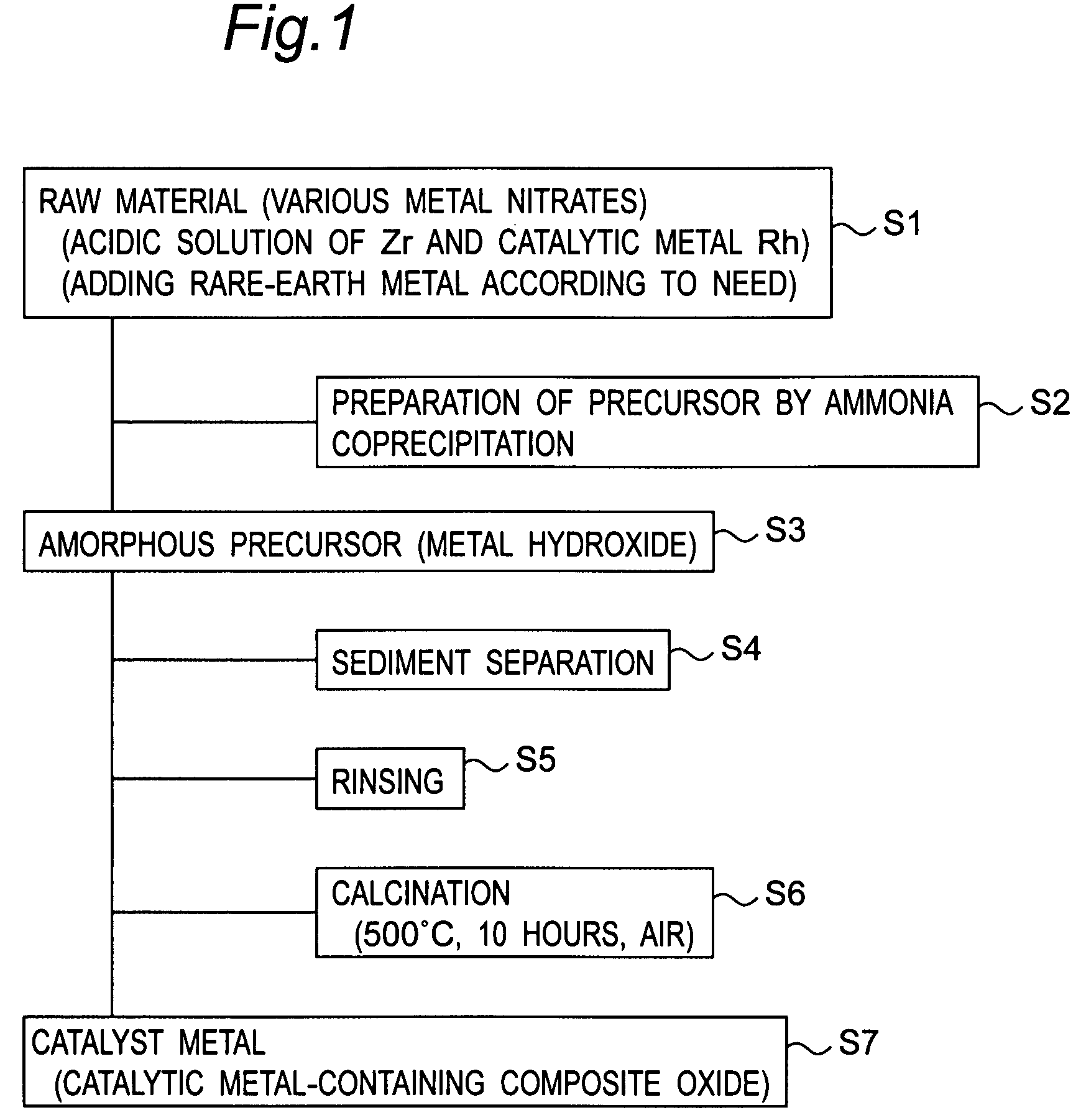
In view of the above technical problems, it is an object of the present invention to provide an exhaust gas purifying catalyst and an exhaust gas purifying method, capable of achieving enhanced exhaust gas conversion efficiency using an oxygen-storage material which comprises Rh as a catalytic metal, arranged on a surface of a composite oxide containing Ce and Zr.
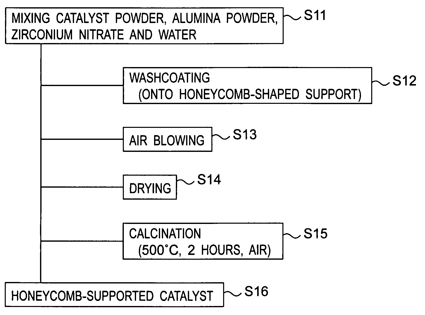
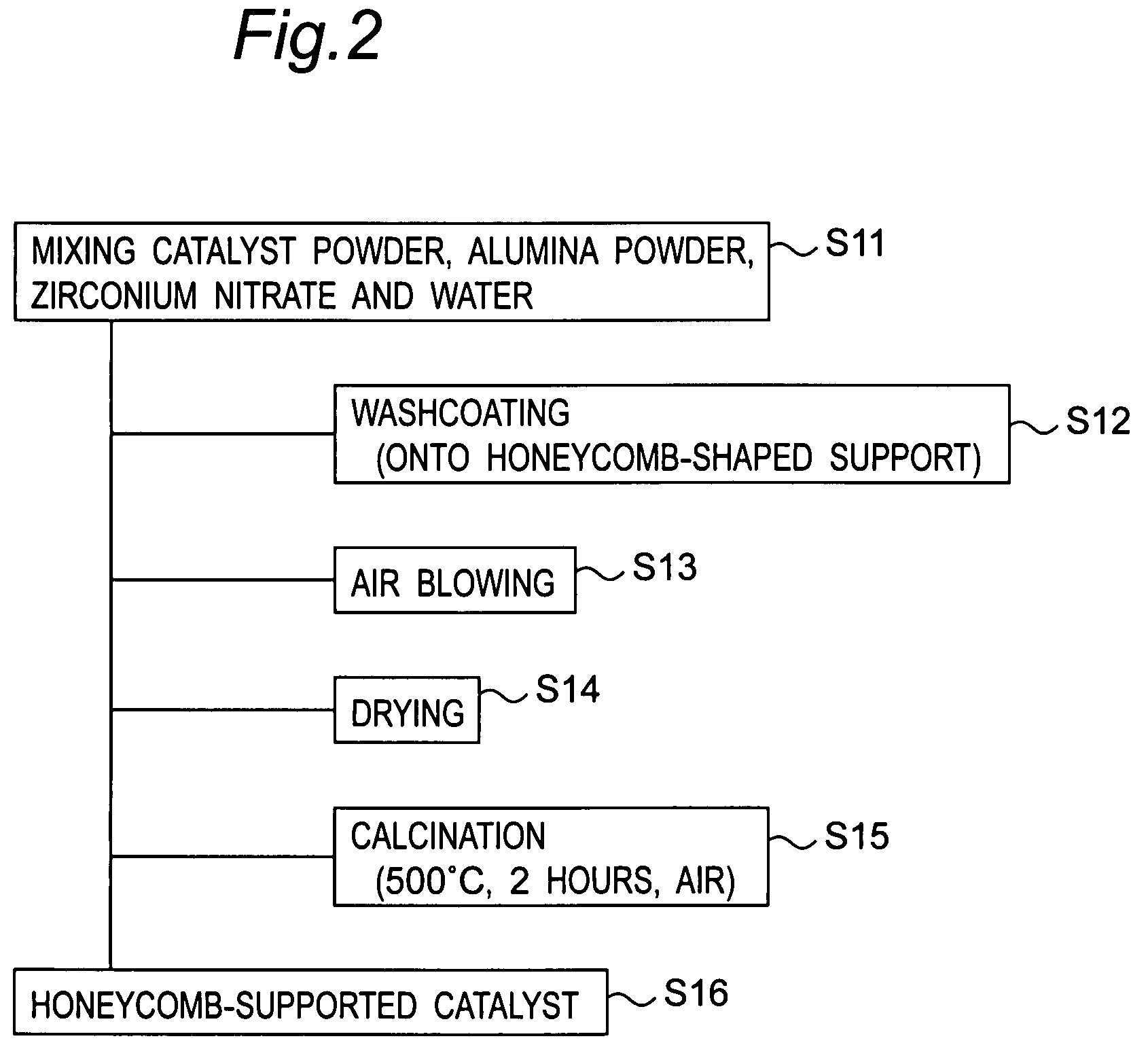
In the exhaust gas purifying method according to the ninth aspect of the present invention, when the exhaust gas purifying catalyst formed by mixing a first catalyst powder (A) consisting of a composite oxide which contains at least Ce, Zr, and a catalytic noble metal composition, and a second catalyst powder (B) consisting of a Zr-based oxide which contains at least Zr and has Rh existing on a surface thereof, is used for purifying exhaust gas, H2 created on the Zr-based oxide of the second catalyst powder (B) is reacted with NOx attached on the composite oxide of the first catalyst powder (A), and a temperature of the catalyst can be increased based on heat generated by the reaction between the H2 and the NOx, to improve low-temperature catalytic activity. Specifically, under a rich (oxygen-deficient) exhaust atmosphere, H2 is created on the Zr-based oxide of the second catalyst powder (B) through a steam-reforming reaction. Although NOx is attached on the composite oxide of the first catalyst powder (A), which contains at least Ce, Zr, and a catalytic metal composition, a part of the NOx is left on the composite oxide in an attached state, because this composite oxide contributes to enhancement in oxygen storage / releasing capability, but has poor NOx reduction function due to a low amount of the catalytic metal composition exposed on a surface thereof, as mentioned above. This meets a condition for readily inducing a reaction between the above created H2 and the attached NOx, and therefore a NOx reduction reaction is facilitated by the created H2 to convert the NOx into inert emissions. Then, the NOx reduction reaction can generate heat to increase a temperature of the catalyst layer so as to achieve enhanced low-temperature conversion efficiency for HC and CO under assistance of oxygen released from the first catalyst powder (A). Thus, the steam-reforming reaction in the second catalyst powder (B) can be utilized positively and effectively for the catalyst powder (A) which consists of a composite oxide containing at least Ce, Zr and a catalytic metal composition.

Problems solved by technology

Thus, as contrasted with an advantage of being able to actively absorb and release oxygen, the composite oxide has a problem about insufficiency of conversion efficiency for exhaust gas emissions absorbed on particles of the composite oxide, particularly in NOx (nitrogen oxides) conversion efficiency, due to limited opportunity of contact between the exhaust gas emissions and the Rh as a catalytic metal.
Particular, in view of an engine cold-start condition causing difficulty in ensuring sufficient catalytic conversion efficiency due to a low catalyst temperature, a catalyst temperature is low, and it is required to improve low-temperature catalytic activity in the exhaust gas purifying catalyst.

Method used


Image

  • Exhaust gas purifying catalyst and exhaust gas purifying method
  • Exhaust gas purifying catalyst and exhaust gas purifying method
  • Exhaust gas purifying catalyst and exhaust gas purifying method

Examples


example 1d

and

FIG. 4 is a graph showing a measurement result of a light-off temperature relating to a HC conversion efficiency of a catalyst in each of Example 2 to Example 5.

FIG. 5 is a graph showing a measurement result of a light-off temperature relating to a HC conversion efficiency of a catalyst in each of Example 6 to Example 9.

FIG. 6 is a graph showing a measurement result of a light-off temperature relating to a CO conversion efficiency of a catalyst in each of Example 1a, Example 1c and Example 1d.

FIG. 7 is a graph showing a measurement result of a light-off temperature relating to a CO conversion efficiency of a catalyst in each of Example 2 to Example 5.

FIG. 8 is a graph showing a measurement result of a light-off temperature relating to a CO conversion efficiency of a catalyst in each of Example 6 to Example 9.

FIG. 9 is a graph showing a measurement result of a light-off temperature relating to a NOx conversion efficiency of a catalyst in each of Example 1a, Example 1c and Example ...


PUM

PropertyMeasurementUnit
temperatureaaaaaaaaaa
lengthaaaaaaaaaa
diameteraaaaaaaaaa

Abstract

Disclosed is an exhaust gas purifying catalyst, which comprises a catalyst layer formed on a honeycomb-shaped support. The catalyst layer is formed by mixing a catalyst powder (A) consisting of a composite oxide (RhZrCeNdO) which contains at least Ce, Zr, and a catalytic noble metal composition, and a catalyst powder (B) consisting of a Zr-based oxide (RhZrXO) which contains at least Zr and has Rh existing on a surface thereof. A ratio (RhZrXO / RhZrCeNdO) of a mass of the catalyst powder (B) to a total mass of the catalyst powder (A) and the catalyst powder (B) may be set in the range of 1 to 50%. Further, the catalyst powder (B) may consist of a composite oxide which contains Zr as a primary component, a rare-earth metal except Ce, and Rh. The exhaust gas purifying catalyst of the present invention can provide enhanced exhaust gas conversion efficiency.

Description

BACKGROUND OF THE INVENTION1. Field of the InventionThe present invention relates to an exhaust gas purifying catalyst and an exhaust gas purifying method.2. Description of the Related ArtWith a view to purifying exhaust gas containing air pollutants, such as HC (hydrocarbon), CO (carbon monoxide) and NOx (nitrogen oxides), an exhaust gas purifying catalyst is provided, for example, in an engine exhaust system of a vehicle, such as an automobile. By use of such an exhaust gas purifying catalyst, HC / CO and NOx can be converted into inert emissions through an oxidation reaction and a reduction reaction, respectively.As a component for use in the exhaust gas purifying catalyst, there has been known an oxygen-storage material which has a property (so called “oxygen storage / releasing capability”) capable of absorbing and storing oxygen in exhaust gas when an exhaust atmosphere is in an oxygen-excess state, i.e., an exhaust air / fuel (A / F) ratio is on a lean side relative to a theoretical ...

Claims


Application Information

Patent Timeline
Patent Type & Authority Patents(United States)
IPC IPC(8): B01J23/10B01J21/06
CPCB01D53/945B01J21/066B01J23/63B01J35/04B01J35/1019B01J35/1061B01J37/038F01N3/2828B01D2255/1025B01D2255/206B01D2255/20715B01D2255/40B01D2255/407B01J2523/48Y02T10/22B01J2523/00Y02T10/12B01J2523/3718B01J2523/822B01J2523/3725B01J2523/3706B01J2523/3737B01J2523/36B01J2523/3787
Inventor MINOSHIMA, KOJIYAMADA, HIROSHIMIYOSHI, SEIJIIWAKUNI, HIDEHARUTAKAMI, AKIHIDE
Owner MAZDA MOTOR CORP
Why Eureka
Eureka Blog
Learn More