Adjusting method and circuit using the same

a technology of circuit and adjusting method, applied in logic circuit coupling/interface arrangement, pulse technique, instruments, etc., can solve the problems of higher power consumption, higher electromagnetic interference (emi), higher power noise, etc., and achieve lower electromagnetic interference (emi), lower power noise, and lower power consumption

Active Publication Date: 2011-01-04
MACRONIX INT CO LTD
View PDF6 Cites 20 Cited by
  • Summary
  • Abstract
  • Description
  • Claims
  • Application Information

AI Technical Summary

Benefits of technology

[0007]The invention is directed to an adjusting method and an adjusting circuit for adjusting driving ability of an output buffer. Compared with the conventional output buffer, the output buffer using the adjusting method and the adjusting circuit according to the invention has the advantages including the lower power noise, the lower power consumption and the lower electromagnetic interference (EMI).

Problems solved by technology

So, the output buffer has the drawbacks including the higher power noise, the higher power consumption and the higher electromagnetic interference (EMI).

Method used


Image

  • Adjusting method and circuit using the same
  • Adjusting method and circuit using the same
  • Adjusting method and circuit using the same

Examples


Embodiment Construction

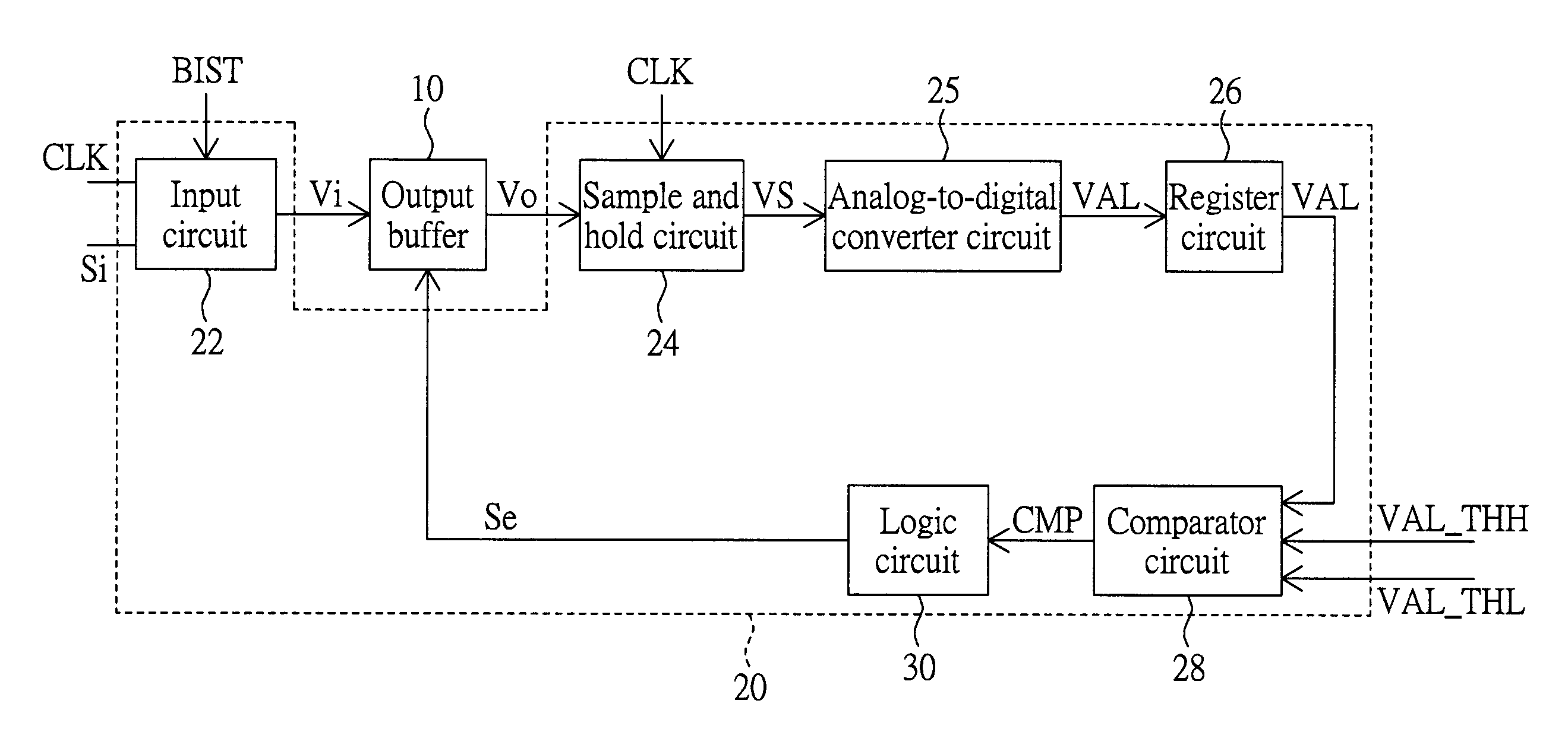
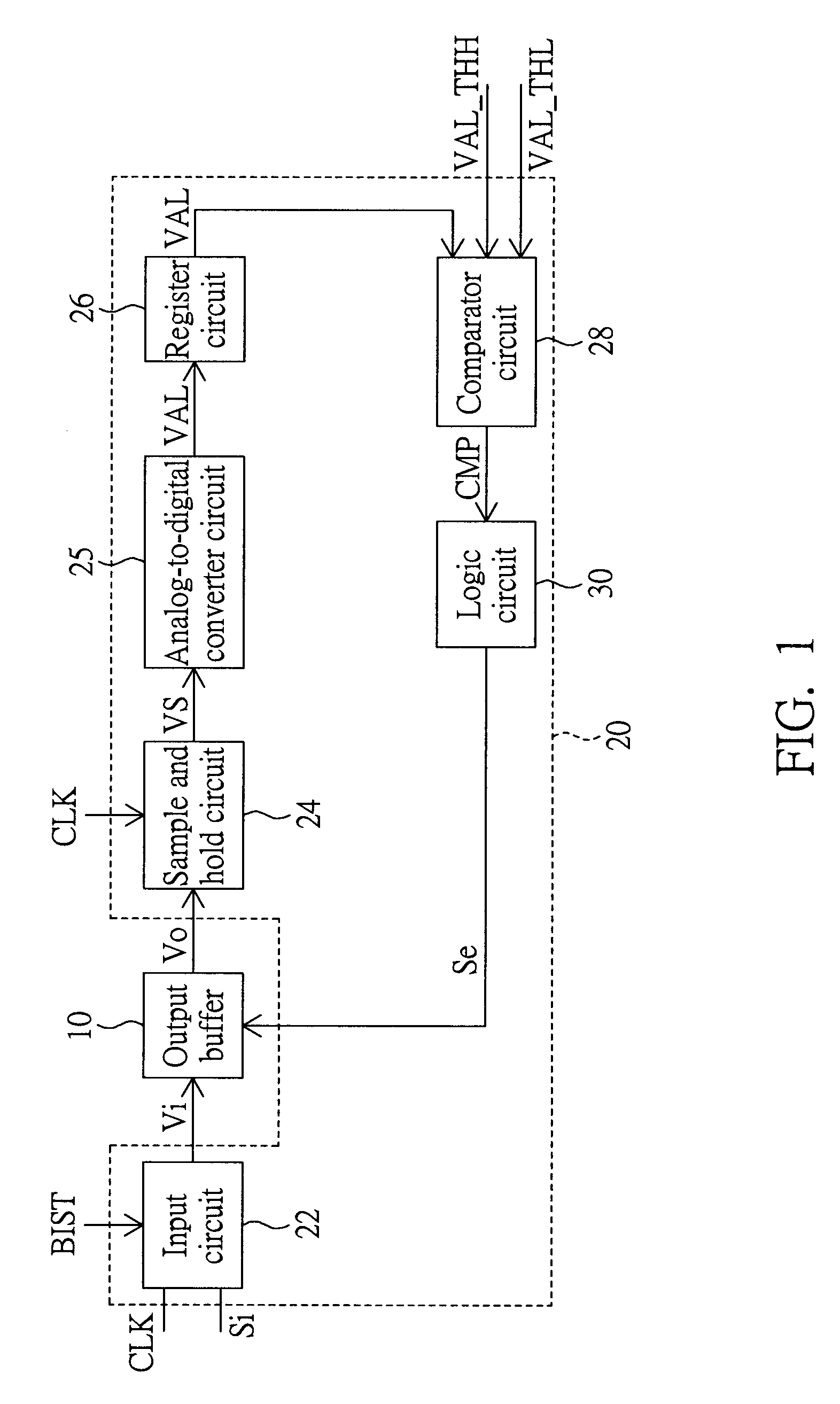
[0018]The adjusting method of this embodiment is used to adjust driving ability of an output buffer when the output buffer is disposed in a circuit environment applied thereto.

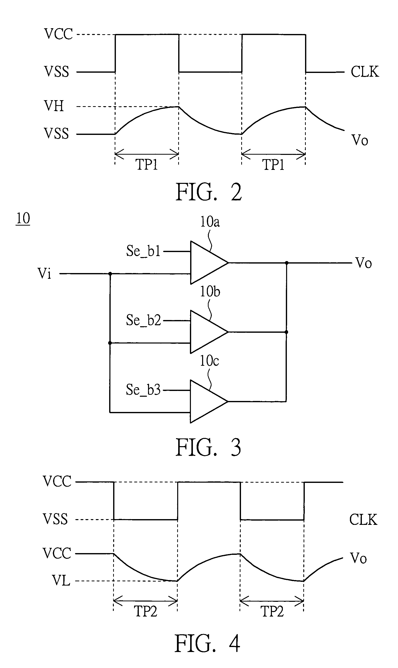
[0019]FIG. 1 is a block diagram showing an adjusting circuit 20 according to an embodiment of the invention. FIG. 2 is a timing chart showing associated signals of the adjusting circuit 20 of FIG. 1. As shown in FIGS. 1 and 2, the adjusting circuit 20 is for adjusting driving ability of an output buffer 10. The output buffer 10 may be, for example, a clock-based output buffer having a value determining period associated with a reference clock signal. For example, the value determining period of the output buffer 10 is substantially equal to a half cycle of a clock signal CLK. In other words, the output buffer 10 adjusts an output voltage Vo from its initial level to a high level judging voltage VOH or a low level judging voltage VOL in one half cycle of the clock signal CLK so that the circuit following and co...


PUM


Abstract

A method adjusts driving ability of an output buffer. The output buffer has multiple driving ability classes. The method includes the following steps. First, the driving ability of the output buffer is initialized as an initial class among the driving ability classes. Next, a voltage at an output terminal of the output buffer is initialized to an initial voltage. Then, an input voltage is inputted via the input terminal at a first time instant. Next, an output voltage outputted from the output terminal is sampled to obtain a voltage value at a second time instant. Then, whether the voltage value satisfies a predetermined condition is judged. Next, if the voltage value satisfies the predetermined condition, the driving ability class of the output buffer is recorded and set.

Description

BACKGROUND OF THE INVENTION[0001]1. Field of the Invention[0002]The invention relates in general to a circuit adjusting method and an adjusting circuit, and more particularly to an adjusting method and an adjusting circuit for adjusting driving ability of an output buffer.[0003]2. Description of the Related Art[0004]In the modern age having the technological development, which changes with each passing day, existing output buffers have been widely used in various occasions. The present output buffer adjusts an output signal from its initial level to a readable high reference level or a readable low reference level according to an input signal in a signal value determining period. In other words, the output buffer needs to have a specific output slew rate so as to adjust the level of the output signal in the signal value determining period.[0005]Generally speaking, the output slew rate of the output buffer relates to parameters, such as process, voltage, temperature and capacitance-l...

Claims


Application Information

Patent Timeline
Patent Type & Authority Patents(United States)
IPC IPC(8): H03K19/094
CPCH03K19/01
Inventor LIN, YUNG-FENG
Owner MACRONIX INT CO LTD
Why Eureka
Try Eureka