System, program product, and related methods for registering three-dimensional models to point data representing the pose of a part

a three-dimensional model and pose technology, applied in the field of three-dimensional scanning, can solve the problems of adversely increasing the manufacturing cost associated with composite structures, requiring strict quality control procedures in manufacturing processes, and expensive conventional nde methods, etc., and achieve the effect of improving the visualization of inspection data

Active Publication Date: 2011-01-04
LOCKHEED MARTIN CORP
View PDF9 Cites 22 Cited by
  • Summary
  • Abstract
  • Description
  • Claims
  • Application Information

AI Technical Summary

Benefits of technology

[0013]In view of the foregoing, embodiments of the present invention advantageously provide a system, program product, and methods to perform automated three-dimensional model registration, which allows both noisy and incomplete sensor data to be automatically registered without manual designation of the areas of correspondence and without ad hoc filtering of the data sources. Embodiments of the present invention also advantageously provide a system, program product, and methods to perform automated three-dimensional model registration, which allow noisy sensor data to be used, as it is, without modification, without identifying areas of interest and without an identification of initial point correspondences between the model and the range (sensor) data. Embodiments of the present invention also advantageously provide a system, program product, and methods which provide for acquisition of a model and a set of sensor data, positioning the model data close to the correct position with respect to the sensor data, and application of an algorithm on the model and sensor data whereby the final transformation represents the registration of the model to the sensor data. Embodiments of the present invention improve upon application of the “Iterative Closest Point” (ICP) algorithm by providing a mechanism to automatically reject outliers and bridge holes in noisy and incomplete sensor data, for example, using two applications of the ICP algorithm, e.g., swapping the source and target.
[0016]The operation of performing a registration of the three-dimensional model to the range data can include utilizing data points on the model of the part defining model data as a source and the range data as a target, and determining the set of points in the range data having a high probability of corresponding to actual points on the model and a transformation “T1” therebetween. The set of points in the range data having a high probability of corresponding to actual points on the model can be a set of points in the range data that are closest to corresponding points in the model as calculated using an iterative closest point algorithm. The operation of performing a registration of the identified set of points in the range data having a high correspondence probability to the three-dimensional model can also include utilizing the identified set of points in the range data as a source and the model data as the target, and determining a transformation “T2” therebetween, and the operation of aligning can include determining a composition of the transformation T1 and an inverse of the transformation T2 to register the part with the three-dimensional model of the part. Advantageously, the registration of the part with the three-dimensional model of the part provides a robust match independent of both an existence of outliers in the range data and missing data in the range data. Further, advantageously, the operation of aligning the three-dimensional model of the part to the measured pose of the part within the inspection cell is performed without pre-filtering the range data to remove outliers or a pre-accounting for missing data.
[0017]Embodiments of the present invention also include methods of performing automated three-dimensional image registration of a part remotely positionable within an inspection cell. According to an embodiment of such a method, the method can include the steps of determining a location of a plurality of points on at least one surface of a part to be inspected when positioned within the inspection cell defining range data, identifying a set of points in the range data having a high probability of corresponding to data points on a three-dimensional model of the part to be inspected, determining a first transformation T1 between the data points on the three-dimensional model and the set of points in the range data having a high probability of corresponding to actual points on the model, such as, for example, to remove outliers, determining a second transformation T2 between the set of points in the range data having a high probability of corresponding to actual points on the model and the data points on the three-dimensional model, such as, for example, to account for missing data-removes bias if model covers more of the part than the range data. The steps can also include determining a composition of the first transformation with an inverse of the second transformation to thereby align the three-dimensional model with the part at part pose, and associating gathered inspection data onto the three-dimensional model at the part pose to provide enhanced visualization of the inspection data.
[0018]Embodiments of the present invention also include computer readable media that is readable by a computer to perform automated three-dimensional image registration of a part. According to an embodiment of the computer readable medium, the computer readable medium can include a set of instructions that, when executed by the computer, cause the computer to perform the operations of retrieving or otherwise receiving model data for a three-dimensional model of the part, retrieving or otherwise receiving data representing points on at least one surface of a part when in a measured pose within the inspection cell defining range data, aligning the three-dimensional model of the part to the measured pose of the part, associating gathered inspection data onto the three-dimensional model at the part pose to provide enhanced visualization of the inspection data, and mapping the inspection data into the model at the part pose responsive to registration of the part to the three-dimensional model of the part.

Problems solved by technology

While composite materials offer significant improvements in performance, they require strict quality control procedures in the manufacturing processes.
Conventional NDE methods, however, have traditionally been labor-intensive, and costly.
As a result, testing procedures have adversely increased the manufacturing costs associated with composite structures.
Recognized by the Applicants, however, is that registration of three-dimensional models to point data representing the pose of a part is complicated by a combination of two fundamental characteristics of the sensor data.
These points can arise from noise in the sensor, or from other objects in the scene such as occluding surfaces, walls, tabletops, and etc.
The second is the absence of data for sections of the model arising, perhaps, from places where the part was occluded or that were out of range of the sensor.
Such techniques, however, reduce efficiency and increase the amount of time necessary to perform the registration, if registration is even possible.
If, however, points exist in the source that are “far” from any true correspondence in the target, the minimization of the transform based on the chosen “false” correspondence can inhibit actual registration.
In particular, when sensor data containing outliers is chosen to be the source, the outliers do not have true correspondences with the model and the registration fails.
Similarly, when the sensor data does not completely cover the model, using the model as the source fails.

Method used


Image

  • System, program product, and related methods for registering three-dimensional models to point data representing the pose of a part
  • System, program product, and related methods for registering three-dimensional models to point data representing the pose of a part
  • System, program product, and related methods for registering three-dimensional models to point data representing the pose of a part

Examples


Embodiment Construction

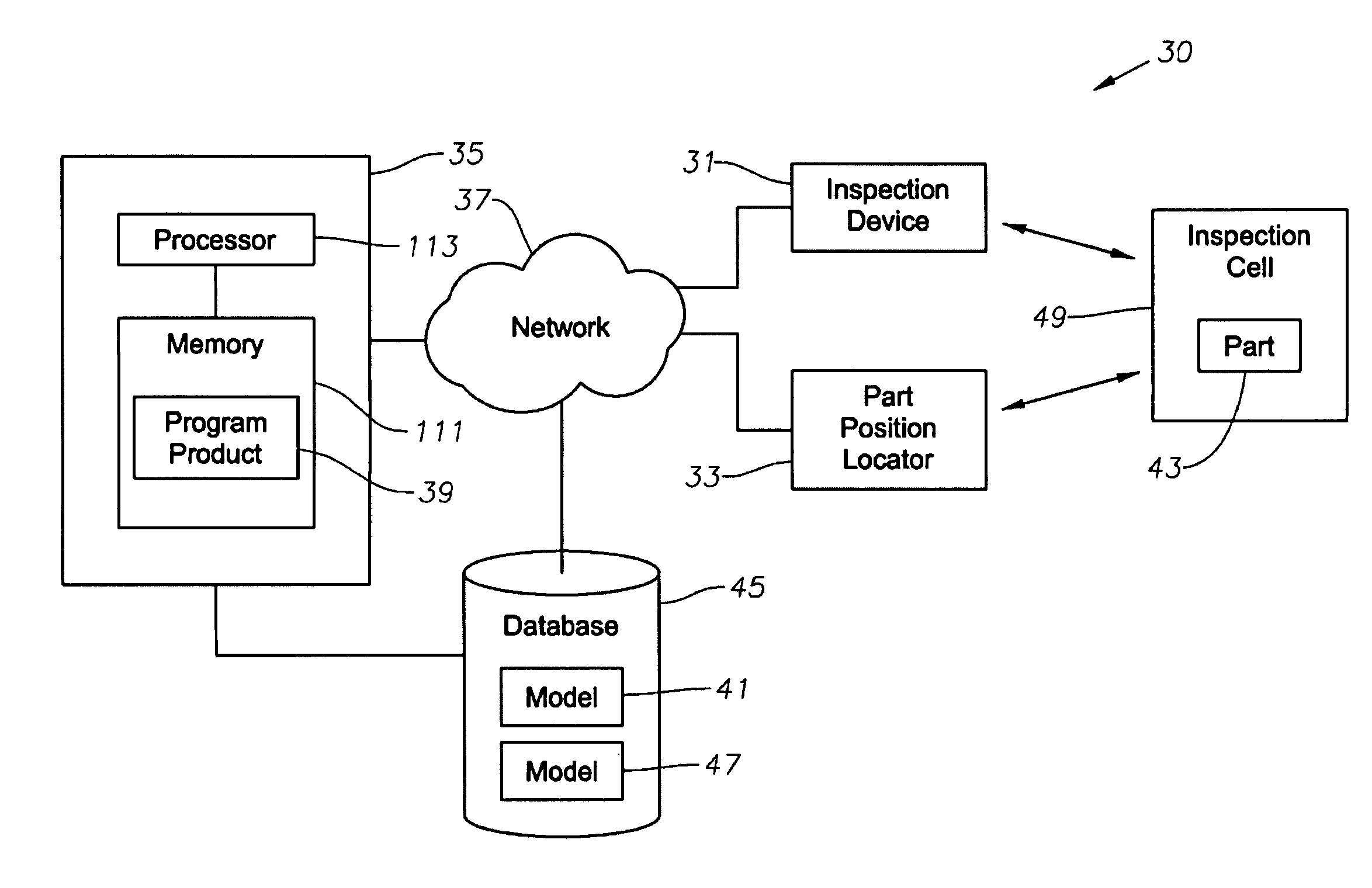
[0030]The present invention will now be described more fully hereinafter with reference to the accompanying drawings, which illustrate embodiments of the invention. This invention may, however, be embodied in many different forms and should not be construed as limited to the illustrated embodiments set forth herein. Rather, these embodiments are provided so that this disclosure will be thorough and complete, and will fully convey the scope of the invention to those skilled in the art. Like numbers refer to like elements throughout.

[0031]Various systems such as non-destructive evaluation systems can use or employ a wide area, imaging device. Such systems also use, for example, a three-dimensional scanner to locate the part within a work cell. The three-dimensional scanner, for example, can create a point cloud of geometric samples (“point data”) on the surface of the part. Such point data can represent the pose of a part in a given environment (“sensor data”). The point data is usual...


PUM


Abstract

A system, program product, and method to perform automated three-dimensional image registration of a part within an inspection cell, are provided. The system can include a laser-ultrasound inspection device having a scanning head to generate ultrasonic surface displacements in a part, an inspection laser, and an interferometer to collect phase modulated light reflected by the part. The system can also include a part position locator positioned to measure a distance between points on a surface of the part and a scanning laser reference location. The system can also include a database containing computer-aided design models for each part of interest, and a model of the inspection cell. The system can further include a laser ultrasound inspection computer communication with the laser-ultrasound detection device and the part position locator, and laser ultrasound inspection program product adapted to perform automated three-dimensional image registration of the part.

Description

CROSS-REFERENCE TO RELATED APPLICATIONS[0001]This non-provisional application claims priority to and the benefit of U.S. Provisional Patent Application No. 61 / 040,415, filed Mar. 28, 2008, titled “ System, Program Product, and Related Methods for Registering Three-Dimensional Models to Point Data Representing the Pose of a Part.”BACKGROUND OF THE INVENTION[0002]1. Field of the Invention[0003]The present invention relates to three-dimensional scanning, and specifically to systems, program product, and methods to perform three-dimensional model registration.[0004]2. Description of Related Art[0005]In recent years, the use of various structures such as, for example, advanced composite structures have experienced tremendous growth in the aerospace, automotive, and many other commercial industries. While composite materials offer significant improvements in performance, they require strict quality control procedures in the manufacturing processes. Specifically, non-destructive evaluation...

Claims


Application Information

Patent Timeline
Patent Type & Authority Patents(United States)
IPC IPC(8): G01B5/30
CPCG01N29/0654G01N29/30G01N29/2418G01B11/24G01N29/24G06T19/20
Inventor TURNER, WESLEYMILLER, JAMESLORENSEN, WILLIAM
Owner LOCKHEED MARTIN CORP
Why Eureka
Try Eureka