Friction stir welding apparatus, system and method

a stir welding and friction stir technology, applied in the field of metal fusion, can solve the problems of reducing so as to reduce the amount of circumferential friction stir welding used, increase the efficiency of welding, and reduce the effect of manpower

Active Publication Date: 2011-01-11
UNITED LAUNCH ALLIANCE
View PDF82 Cites 43 Cited by
  • Summary
  • Abstract
  • Description
  • Claims
  • Application Information

AI Technical Summary

Benefits of technology

Other Advantages of Embodiments of the Present Invention
It is another aspect of the present invention to provide a system that increases the amount of circumferential friction stir welds used in an object to be welded, without the associated costs associated therewith. For example, such a system relieves manpower associated with a welding task by removing the need to move tooling, backing members, etc. More specifically, in the realm of launch vehicle production, propellant tanks are generally comprised of cylindrical barrel segments each comprised of longitudinally welded barrel panels. The barrel segments are capped by end domes to form a propellant tank. The portions of some pressure-stabilized tanks are joined by resistance welds. Heavier, thicker structurally stable barrel segments must be joined by other techniques such as arc welding, which requires filler. Typically, a booster segment, which comprises at least two propellant tanks, fourteen or more circumferential welds are required, i.e., between sumps and domes, domes and skirts, domes and barrels, barrel segments and barrel, segment and barrel and dome. The contemplated apparatus and methods disclosed herein may be used to weld more of the circumferential welds of a booster tank.
It is another improvement of the present invention to provide a system of increasing weld efficiency. More specifically, with respect to booster tank construction, the prior art method involves the welding of barrel sections in various orientations, which increases the time and complexity of fabrication. Generally, barrels that make up the booster tank/propellant tanks are comprised of a plurality of flat panels that are bent and then welded to form a cylindrical barrel segment. The longitudinal welds of the barrel segment are often traditional linear friction stir welds. Typically, barrel segments, cylindrical skirts, and dome sections are welded in a vertical orientation wherein the components are rotated relative to a traditional welding tool to create portions of the propellant tank. Various skirts, adapters, domes, etc. are also welded in this fashion. The tank portion...

Problems solved by technology

Further, this technique also provides welds with extremely low dimensional distortion.
Friction between the rotating pin and work pieces causes localized heating and plasticizing of the material adjacent to the pin.
One drawback with friction stir welding is associated with the considerable force that must be exerted by the stir welding tool on the work piece.
Without the use of a counteracting backing member, tank distortions and inadequate weld penetration can result.
Another disadvantage with friction stir welding is that the end weld is incomplete because a hole associated with the pin remains when the friction stir welding tool is removed from the joint.
It is a related disadvantage of friction stir welding that the ...

Method used


Image

  • Friction stir welding apparatus, system and method
  • Friction stir welding apparatus, system and method
  • Friction stir welding apparatus, system and method

Examples


Embodiment Construction

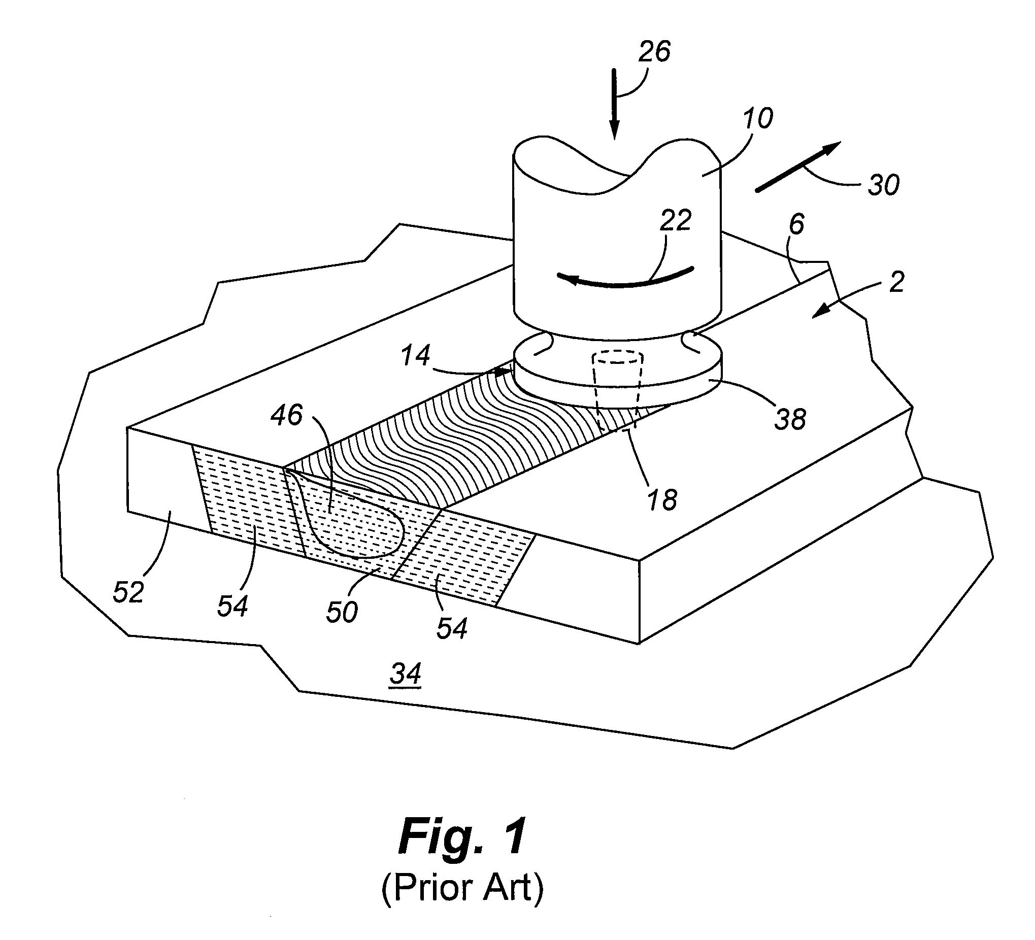
Referring now to FIG. 1, a prior art friction stir weld technique is illustrated wherein work pieces 2 are abutted to form a joint 6 therebetween. A friction stir welding tool includes a head 10 with associated shoulder 14 and pin 18. In practice, the shoulder 14 is placed on the work pieces 2 and the pin 18 is placed within the joint 6 after sufficient heat is generated by the spinning tool to allow penetration thereof. The head 10 is then forced downwardly onto the work pieces 2 as indicated by arrow 26 and is transitioned relative thereto 30. One skilled in the art will appreciate that the work pieces 2 may also move relative to the rotating head 10. The force 26 generated by the head 10 is reacted by a backing bar 34. As the head 10 is rotated and moved forward in the direction 30, friction is generated by the shoulder 14 and the pin 18 which keeps the metal of a portion of both work pieces 2 such that metal adjacent to a leading edge 38 of the shoulder 14 is moved / displaced to ...


PUM

PropertyMeasurementUnit
Lengthaaaaaaaaaa
Distanceaaaaaaaaaa
Forceaaaaaaaaaa

Abstract

A method of performing friction stir welding is provided herein. More specifically, traditional friction stir welding requires a rotatable head that is forced against a plurality of work pieces to bond the same. The rotational and normal forces generated by the friction stir welding tool are generally reacted by a backing plate, anvil, mandrel or other mechanisms, such hardware are subject to the applied forces and are often supported with additional internal supports. Conversely, a method of performing a friction stir weld is described that omits the need for such a backing member and internal supports as it is performed using a self reacting pin tool.

Description

FIELD OF THE INVENTIONEmbodiments of the present invention are related generally to metal fusion using a dynamic weld head to bond arcuate work pieces. More specifically, a weld fixture with external support rings holds the work pieces and a self-reacting friction stir welding tool bonds cylindrical shaped work pieces wherein a backing member is not required to counteract forces generated by the weld tool.BACKGROUND OF THE INVENTIONFriction stir welding is a beneficial metal bonding technique wherein materials such as aluminum 7075, various alloys of aluminum / lithium and other similar materials previously considered to be unweldable, can be bonded. Friction stir welding also forms joints that possess material properties similar to those of the parent materials. Further, this technique also provides welds with extremely low dimensional distortion.Unlike fusion welding, in which portions of each work piece being joined are melted and then resolidified to form a new and different mater...

Claims


Application Information

Patent Timeline
IPC IPC(8): B23K20/12B23K37/04
CPCB23K20/122B23K20/126B23K37/0533B23K2201/06B23K2101/06
Inventor POTTER, DAVID M.HANSEN, RICHARD K.
Owner UNITED LAUNCH ALLIANCE
Why Eureka
Try Eureka