
Light emitting device with translucent semi-reflection layer and electronic apparatus

a technology of semi-reflection layer and light emitting device, which is applied in the direction of discharge tube/lamp details, discharge tube/solid-state device testing/measurement, discharge tube luminescnet screen, etc., can solve the problem of reducing the reflection of light having colors similar to the colors of light emitted from organic el elements, deteriorating display image quality, brightness deterioration, etc. problem, to achieve the effect of reducing the reflection of external light and high quality

Active Publication Date: 2011-01-11
ELEMENT CAPITAL COMMERCIAL CO PTE LTD
View PDF13 Cites 13 Cited by
  • Summary
  • Abstract
  • Description
  • Claims
  • Application Information

AI Technical Summary

Benefits of technology

"The invention provides a light emitting device and an electronic apparatus including the light emitting device that can solve problems such as image quality deterioration caused by external light incident on the device. The device includes a light emitting element, a reflection layer, and a translucent semi-reflection layer, which can reflect light emitted from the light emitting element and transmit some of it. The translucent semi-reflection layer has a refractive index of 1 or more, which reduces the amount of reflected external light. The device also includes a color filter to transmit the light transmitted through the translucent semi-reflection layer. The optical distance between the reflection layer and an interface opposite it in the translucent semi-reflection layer is determined to achieve the attenuated interference effect. The device can be manufactured with a positive adjustment of the physical thickness of the translucent semi-reflection layer to control the refractive index."

Problems solved by technology

However, the organic EL element has a problem with deterioration of a display image quality caused due to external light reflecting from a display surface.
However, since the circular polarizing plate attenuates light generated in a light emitting layer to a half or less, a problem may also occur in that brightness deteriorates.
However, such a method of just using the color filter can reduce the reflection of light having colors different from colors of light emitted by the organic EL element, but cannot reduce the reflection of light having colors similar to colors of light emitted from the organic EL element that much.
However, Japanese Patent No. 3944906 has a problem in that the reflected light may be reduced due to attenuated interference when the phase of the reflected light in one layer and the phase of the reflected light in another layer are reversed from each other.
Moreover, there is a limit to an increase in efficiency of the light emitted from the organic light emitting element under such a condition.
However, even in the structure in which light reciprocates between the electrodes, the light is not resonated, and thus use efficiency of light may not be improved if an optical factor such as an optical distance is not appropriate.

Method used

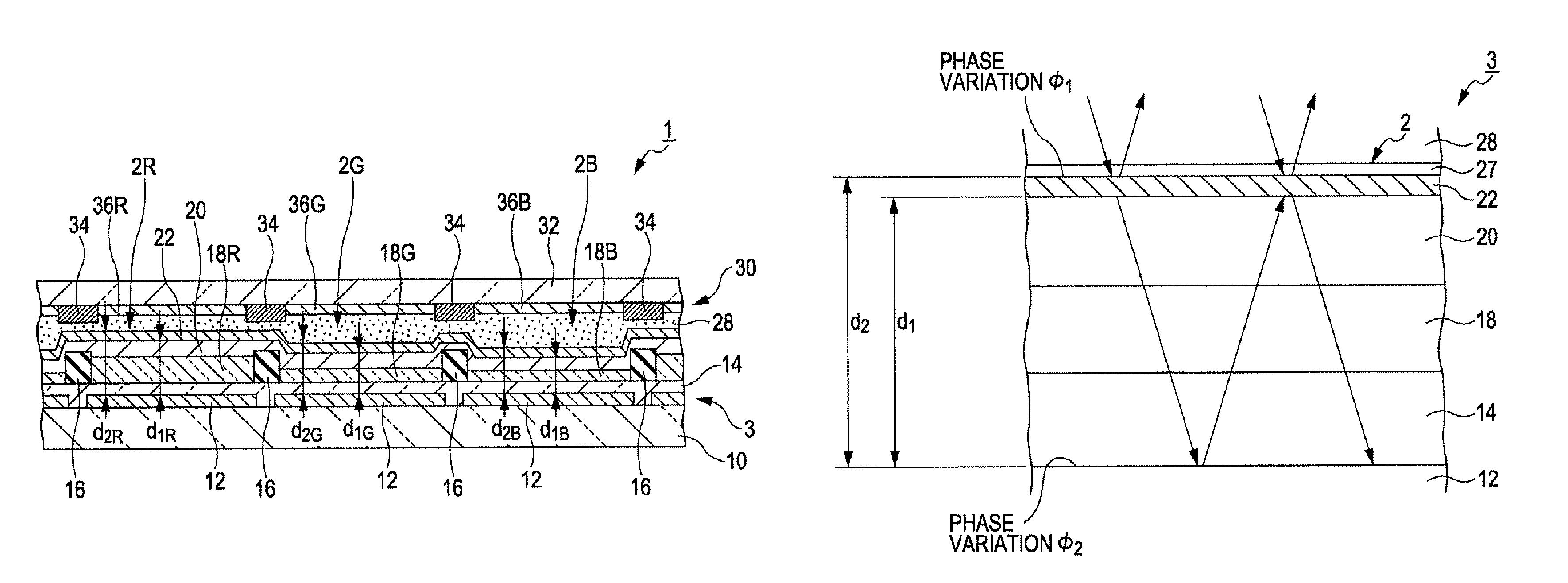
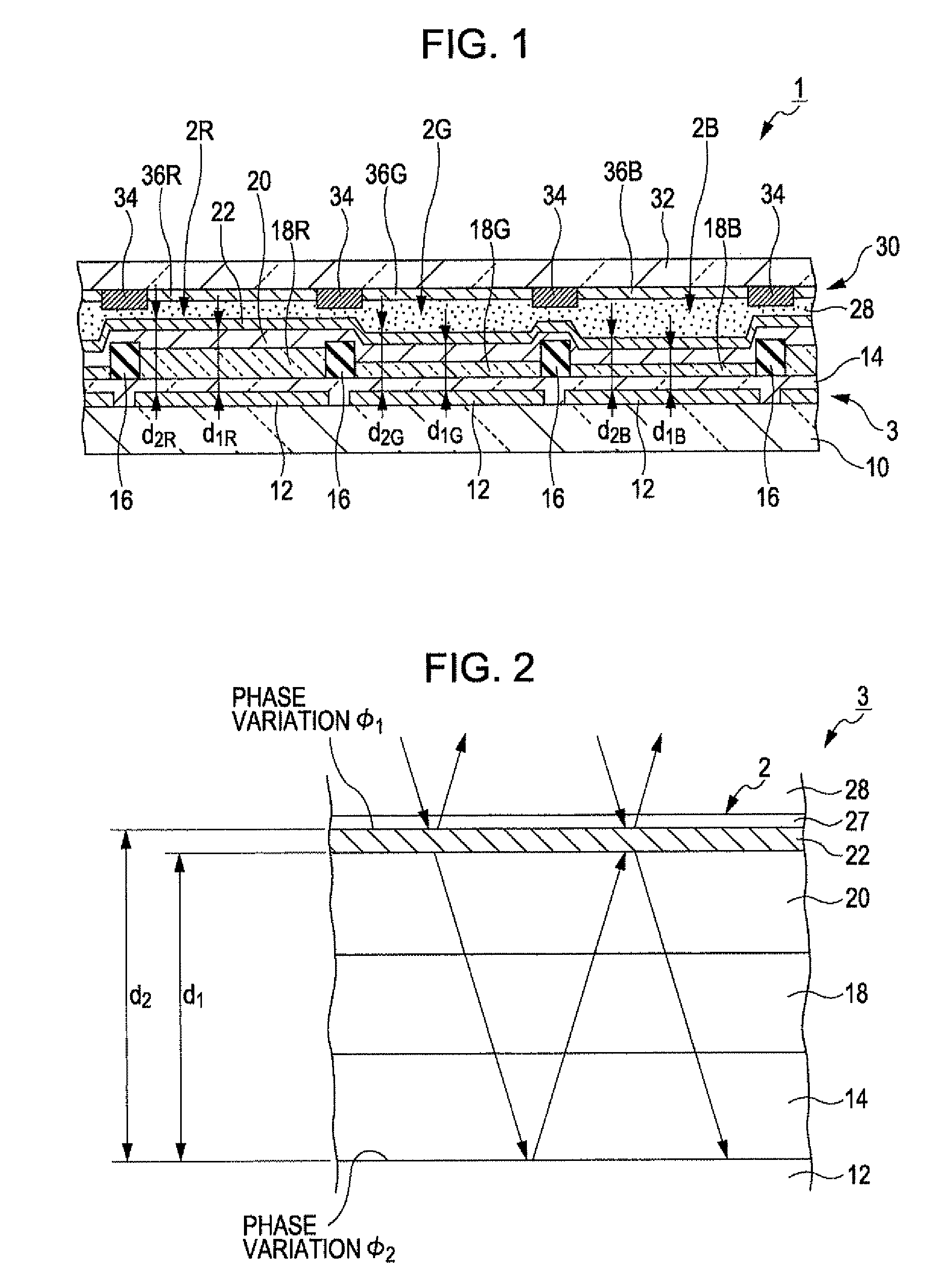
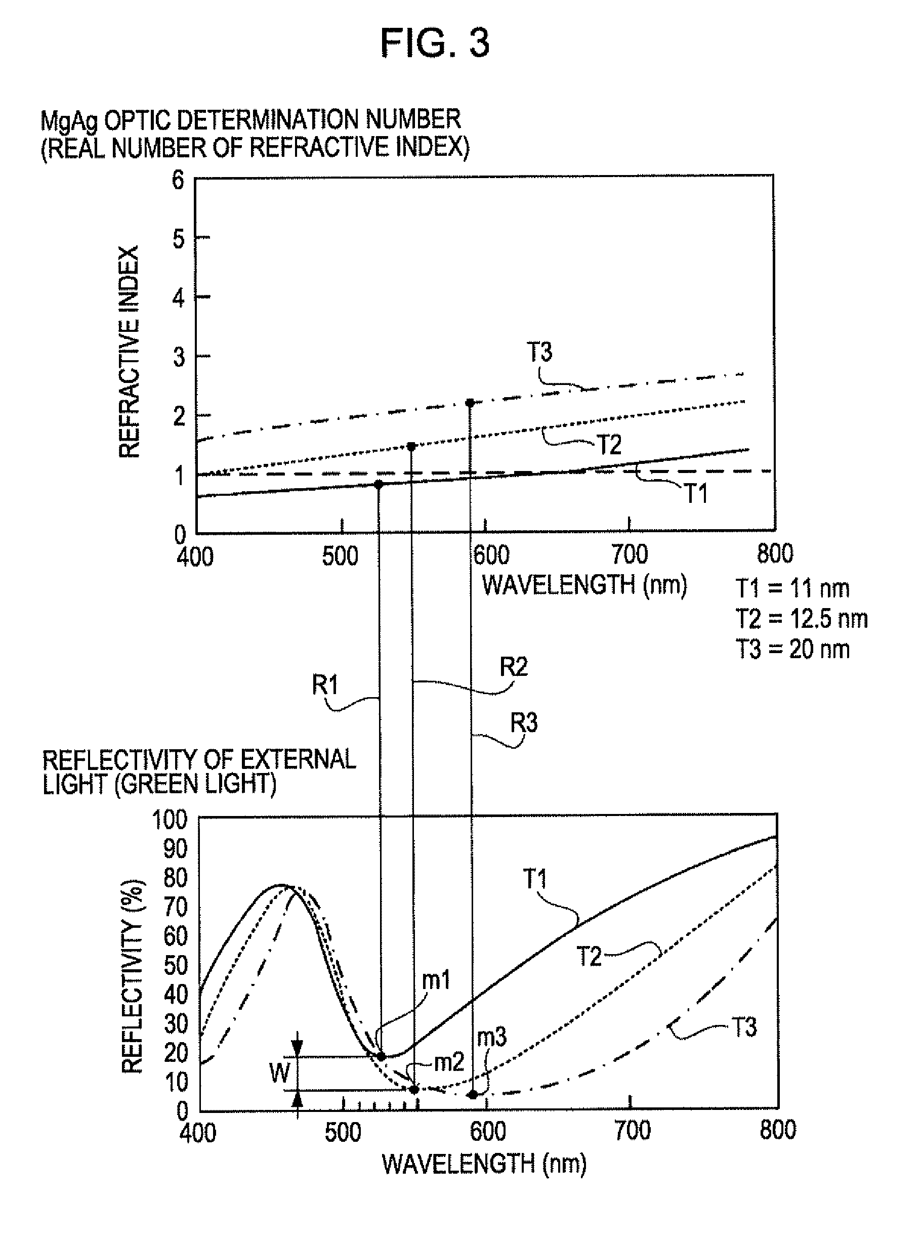

Image

  • Light emitting device with translucent semi-reflection layer and electronic apparatus
  • Light emitting device with translucent semi-reflection layer and electronic apparatus
  • Light emitting device with translucent semi-reflection layer and electronic apparatus

Examples


applied example

[0157]Next, an electronic apparatus to which the organic EL device related to the invention is applied will be described. FIG. 18 is a perspective view illustrating a configuration of a mobile personal computer using the light emitting device according to this embodiment as an image display device. A personal computer 2000 includes an organic EL device 100 as a display device and a body unit 2010. The body unit 2010 includes a power supply switch 2001 and a keyboard 2002.

[0158]FIG. 19 shows a cellular phone to which the light emitting device according to this embodiment is applied. A cellular phone 3000 includes a plurality of operational buttons 3001, scroll buttons 3002, and an organic EL device 100 as a display device. A screen displayed on the organic EL device 100 is scrolled by operation of the scroll buttons 3002.

[0159]FIG. 20 shows a PDA (Personal Digital Assistant) to which the light emitting device according to this embodiment is applied. The PDA 4000 includes a plurality ...


PUM


Abstract

A light emitting device includes: a light emitting element which includes a first electrode layer, a second electrode layer, and a light emitting function layer disposed between the first electrode and the second electrode; a reflection layer which reflects light emitted from the light emitting function layer toward the light emitting function layer; and a translucent semi-reflection layer which is disposed opposite the reflection layer with the light emitting function layer interposed therebetween to reflect some of the light emitted from the light emitting function layer toward the light emitting function layer and to transmit the remainder of the light, wherein the translucent semi-reflection layer has a refractive index of 1 or more.

Description

BACKGROUND[0001]1. Technical Field[0002]The present invention relates to a light emitting device which emits light by electroluminescence and an electronic apparatus.[0003]2. Related Art[0004]As a thin lightweight light emitting source, an OLED (Organic Light Emitting Diode), that is, an organic EL (Electro Luminescent) element is popular. Accordingly, an image display device having a plurality of the organic EL elements has been developed. The organic EL element has a structure in which at least one organic thin film layer made of an organic material is interposed between pixel electrodes and counter electrodes.[0005]In a field of the organic EL element, there is a known technique (for example, a PCT pamphlet No. WO01 / 39554) for intensifying light having a specific wavelength in emitted light, using amplified interference, that is, resonance. This technique is capable of improving color purity of luminescent color or improving efficiency of light radiated in response to light emiss...

Claims


Application Information

Patent Timeline
Patent Type & Authority Patents(United States)
IPC IPC(8): H01J5/16H01J61/40H01K1/26H01K1/30
CPCH01L51/5281H10K59/10H10K59/8791H01L22/12H01L2224/05123H10K59/38H10K50/86
Inventor KOBAYASHI, HIDEKAZU
Owner ELEMENT CAPITAL COMMERCIAL CO PTE LTD
Learn More