
Luminaire control system and method

a control system and light source technology, applied in the field of light source, can solve the problems of undesired light effects in feedback-controlled multi-color led based systems, insufficiently accurate responsivities, and inability to provide practical useful indications of cie tristimulus values

Active Publication Date: 2011-01-11
SIGNIFY HLDG BV
View PDF64 Cites 96 Cited by
  • Summary
  • Abstract
  • Description
  • Claims
  • Application Information

AI Technical Summary

Benefits of technology

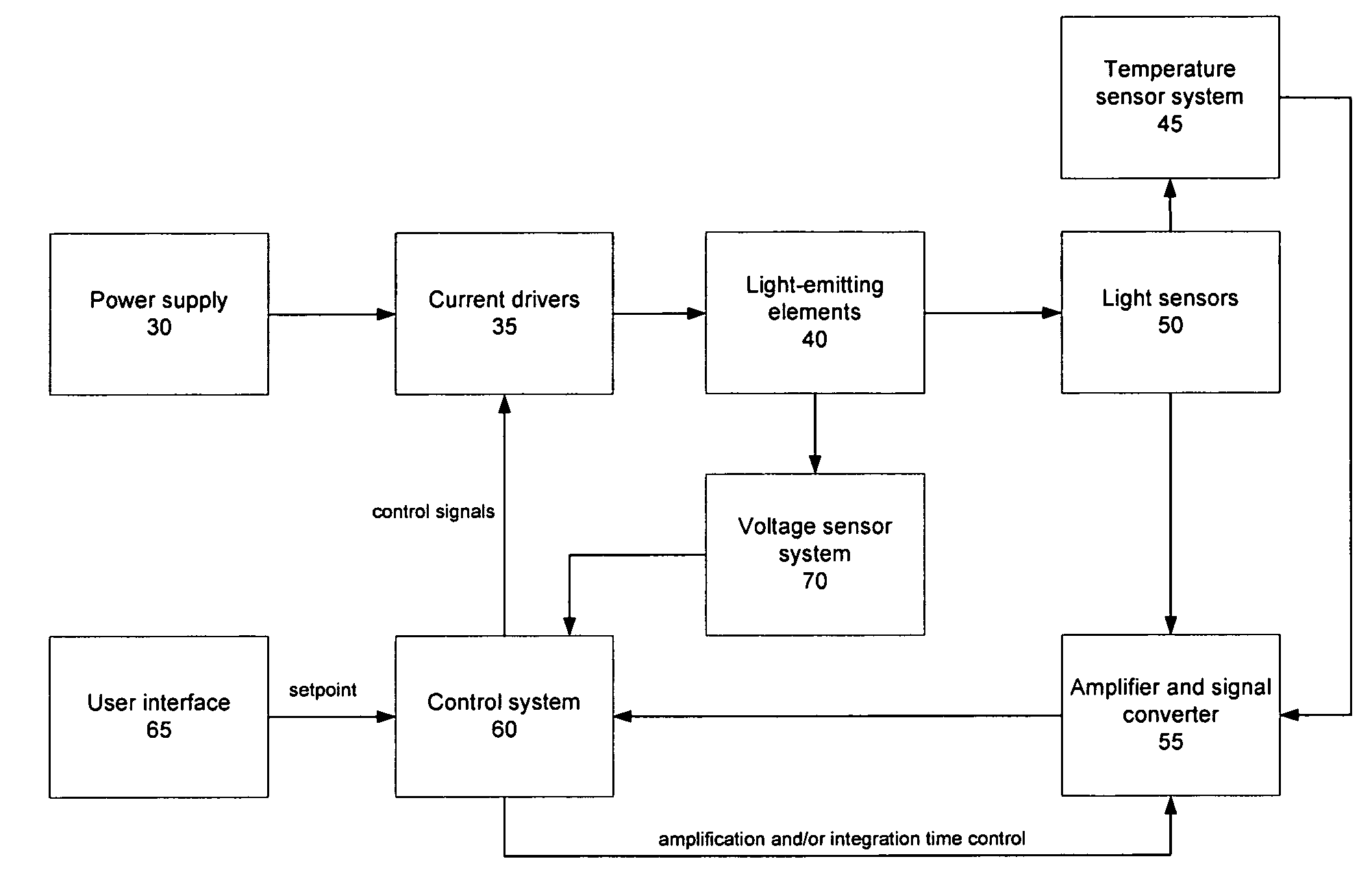
The present invention provides a system and method for controlling light-emitting elements (LEES) to generate a mixed light. The system includes optical sensors to acquire sensor data and a user interface to set the desired mixed light. The sensor data is transformed into coordinates of a predetermined color coordinate system and the setpoint data is also transformed into coordinates of the same system. The two sets of data are then compared, and the difference between them is determined. The forward currents are adjusted accordingly to decrease the difference between the two sets of data until it reaches an absolute value below a predetermined threshold. This invention allows for precise control over the mixed light generated by the LEES.

Problems solved by technology

One of the challenges in solid-state lighting is to design a system and / or method that can set and maintain intensity and chromaticity of the mixed light emitted by a plurality of color, for example, blue and yellow or red, green, and blue LEDs.
This can be challenging as the light emitted by LEDs may vary depending on operating conditions other than the electrical currents provided to the LEDs.
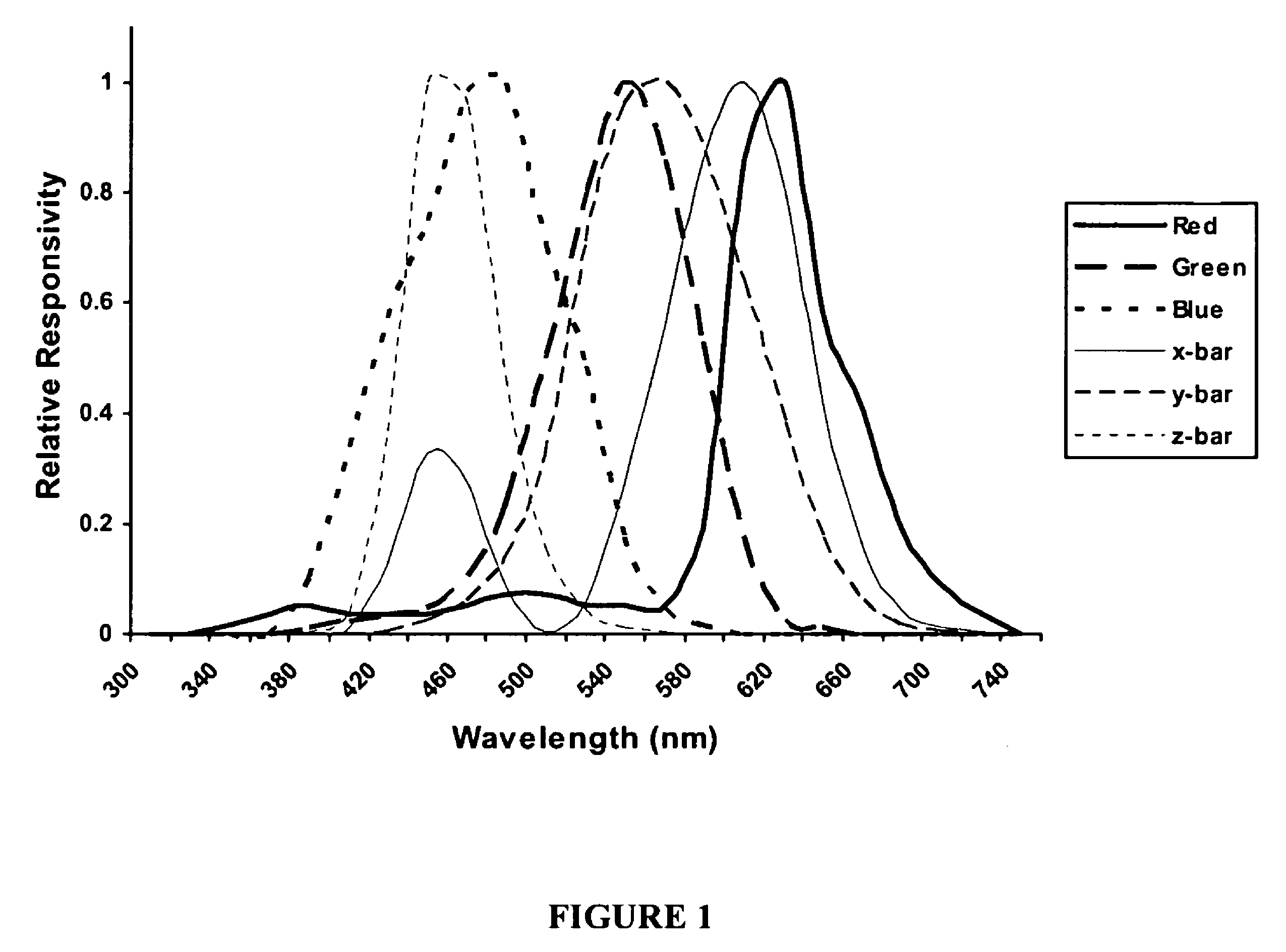
For example, firstly, the spectral responsivities of known cost-effective RGB color sensors do not, for practical purposes, sufficiently closely mimic the spectral responsivity of the human eye.
Spectral mismatches, even smaller than the ones illustrated, can cause undesired light effects in feedback-controlled multi-color LED based systems.
As such tristimulus values determined based on signals provided by RGB color sensors with insufficiently accurate responsivities may not provide practically useful indications of the CIE tristimulus values.
Matching the filters and sensors to accurately reproduce the CIE color matching functions, even under temperature-controlled laboratory conditions, however, is complex.
Therefore, useful filter sensor combinations can be expensive, which are discussed by G. P. Eppeldauer, “A Reference Tristimulus Colorimeter,” Proceedings of the Ninth Congress of the International Color Association of the Optical Engineering Society, SPIE 4421, pp 749-752, (2002), Bellingham, Wash., USA.
Furthermore, feedback control that is only based on CIE tristimulus values does not separate chromaticity (i.e. color) from intensity and therefore may not be effective in suppressing a number of undesired chromaticity fluctuations.
This approach, however, in general does not address how to mitigate undesired effects of RGB sensor spectral responsivity mismatches during operation.
However, Wandell do not teach the use of the least-squares solution with a real-time feedback apparatus, or its application to light source control.
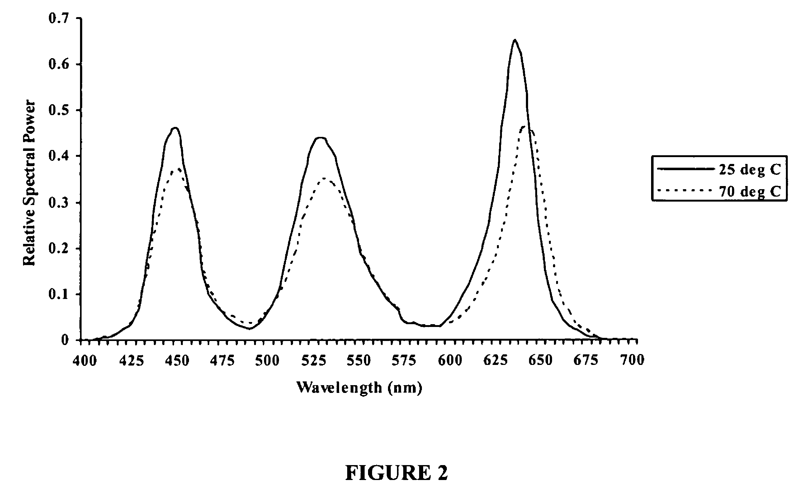
The ambient temperature is once 25° C. and once 70° C. Further to the effects of different operating temperature, different LED drive currents in different color LEDs can result in different rates of power dissipation and consequently different LED junction temperatures.
In addition, thermal coupling between different color LEDs can cause interdependencies between the LED junction temperatures.
Consequently, the well-known Grassman laws of color additivity may not provide accurate descriptions of the color of the mixed light without consideration of self and cross heating effects of the LEDs and any optical sensors employed to sense the generated light.
Luminaire feedback control systems can therefore suffer from a number of effects including the issue that RGB sensors with different sensitivities will provide different unique responses to light of the same SPD.

Method used


Image

  • Luminaire control system and method
  • Luminaire control system and method
  • Luminaire control system and method

Examples


example 1

[0053]In a first example, the control system can be configured to read the RGB sensor data [R G B] and apply a predetermined transformation in order to derive approximate values of the CIE tristimulus values X, Y and Z of the light emitted by the LEEs. This can be performed by, for example, programming the control system with the linear algebraic relation

[XYZ]=[RGB]T  (3)

using the 3×3 transformation matrix

T=(NTN)−1NTM=N+M  (4)

NT is the transpose and N+ is the pseudoinverse of N. M is an n×3 matrix of ideal tristimulus values Mij and N is a corresponding n×3 matrix of RGB color sensor data for the same set of n SPDs. M and N can be determined during a calibration step that utilizes the n SPDs and characterizes them with the RGB color sensors to determine N and, for example, with an accurately calibrated spectrometer to determine M. T can subsequently be determined, for example, through a least squares solution, by minimizing the error function

[0054]=∑i=1n⁢⁢∑j=13⁢⁢(Mi⁢⁢j-[N⁢⁢T]i⁢⁢j)2(...

example 2

[0063]In another embodiment, it may be advantageous in terms of computational efficiency to operate the control system using feedback raw RGB sensor data directly. In such an embodiment, it is no longer necessary for the control system to transform the RGB sensor data each time it is fed back. Instead the user-specified input data is transformed into RGB sensor coordinates from coordinates such as XYZ tristimulus or xyY chromaticity and intensity, for example, in order for the control system to compare the setpoint with the RGB color feedback data. In such an embodiment, a transformation needs to take place only when the user-specified input data changes. In this embodiment the control system operates in RGB sensor coordinates to set and maintain desired chromaticity and intensity.

[0064]For a predetermined transformation T, the target RGB values can be determined from:

[RTGTBT]=[XYZ]T−1  (11)

It is noted that the transformation T used in Equation 11 may the determined as described abo...

example 3

[0066]In this embodiment the controller is configured to transform each of one or more predetermined RGB sensor data into a respective predetermined desired color space, for example XYZ data while the rest of a training set of the RGB sensor data is transformed as described even if the average least squares error for the rest of the data is increased. This embodiment may be utilized to ensure that the control system can perform a calibration process that preserves white light RGB sensor data as such.

[0067]The additional constraint for the calibration method can be expressed as Mw=NwT where Nw is the RGB sensor data of the predetermined “white” SPD, and Mw are the corresponding XYZ tristimulus values. The transformation matrix can be determined by:

[0068]Tj=(NT⁢N)-1⁢NT⁢Mj+(1-MjT⁢N⁡[NT⁢N]-1⁢Nw)(NwT⁡[NT⁢N]-1⁢Nw)⁡[NT⁢N]-1⁢Nw(12)

where Tj is the ith column of T, Mj is the jth column of M, and Mw=[1 1 1].

[0069]In one embodiment the controller is configured with CIE 1976 UCS color space coor...


PUM


Abstract

The present invention provides a system and method for controlling one or more light-emitting elements which are driven by forward currents to generate mixed light for use, for example, through a luminaire. The system has one or more light sensors for acquiring feedback optical sensor data and a user interface for providing reference data representative of a desired mixed light. The system also has a controller for transforming either the sensor data or the reference data into the coordinate space of the other and to determine a difference between the sensor and the reference data in that coordinate space. The controller is configured to adjust the forward currents during operating conditions so that the sensor data matches the setpoint data. The present invention also provides a system and method that can at least partially compensate certain temperature induced effects when transforming the optical sensor or the reference data.

Description

FIELD OF THE INVENTION[0001]The present invention pertains to the field of lighting and in particular to control of color and intensity of light emitted by a light source.BACKGROUND[0002]Advances in the development and improvements of the luminous flux of light-emitting devices such as solid-state semiconductor and organic light-emitting diodes (LEDs) have made these devices suitable for use in general illumination applications, including architectural, entertainment, and roadway lighting. Light-emitting diodes are becoming increasingly-competitive with light sources such as incandescent, fluorescent, and high-intensity discharge lamps.[0003]One of the challenges in solid-state lighting is to design a system and / or method that can set and maintain intensity and chromaticity of the mixed light emitted by a plurality of color, for example, blue and yellow or red, green, and blue LEDs. This can be challenging as the light emitted by LEDs may vary depending on operating conditions other...

Claims


Application Information

Patent Timeline
Patent Type & Authority Patents(United States)
IPC IPC(8): G05F1/00H01L33/00H05B44/00
CPCH05B33/0863H05B33/0869H05B45/22H05B45/28
Inventor SALSBURY, MARCASHDOWN, IANSMITH, DUNCAN L. B.ROBINSON, SHANE P.SPEIER, INGO
Owner SIGNIFY HLDG BV
Learn More