Flyback converter having an active snubber

a technology of active snubber and flyback converter, which is applied in the direction of electric variable regulation, process and machine control, instruments, etc., can solve the problems of affecting the operation of the circuit or switch, and not having synchronous characteristics, so as to reduce the loss and current phase shifting, reduce the loss and resonance, and reduce the effect of circumferential current and resonan

Active Publication Date: 2011-01-11
SPI ELECTRONICS
View PDF8 Cites 32 Cited by
  • Summary
  • Abstract
  • Description
  • Claims
  • Application Information

AI Technical Summary

Benefits of technology

[0003]In view of the aforesaid disadvantages occurred to the conventional techniques, the primary object of the present invention is to provide an active snubber to decrease circumferential current and resonance generated by the snubber to reduce loss and current phase shifting at the secondary side.
[0004]The invention provides a flyback converter equipped with an active snubber. The flyback converter includes a primary winding to receive input power, a primary switch to control current period of the primary winding and a pulse-width modulation (PWM) unit to output a periodic signal. The periodic signal includes an ON period and an OFF period to drive the primary switch. The active snubber is coupled in parallel with two ends of the primary winding and has a first circumferential circuit coupling in parallel with the primary winding, a second circumferential circuit and a zero voltage switch unit in sync with the PWM unit. The first circumferential circuit includes a damping capacitor and a first diode. The diode has an anode bridging the primary winding and the primary switch. The second circumferential circuit is coupled in parallel with two ends of the first diode and includes a damping control switch and an inductor. The first circumferential circuit first provides a current to pass through the damping capacitor to be absorbed thereof after the primary switch is OFF. The zero voltage switch unit receives a detection voltage between the first diode and the damping capacitor and sets a base value to be compared with the detection voltage. Through the synchronous clock of the PWM unit and a damping control signal generated by judging the detection voltage being lower than the base value, the damping control switch is driven and set ON to turn on the second circumferential circuit. Thereby a second damping current circuit is formed to reduce the current, and resonance that might otherwise occur between a single circumferential circuit and the secondary side of the transformer can be prevented.

Problems solved by technology

When the switches are located in the circuits of a higher electric power, occurrence of the spike could damage the circuit or switches.
While the passive snubbers mentioned above and taught in other prior art can eliminate the spike, they are not controlled by signals and do not have synchronous characteristics.
The higher current causes a greater conductive loss and results in other problems because of the loss.
As a result the switches at the secondary side endure a higher spike voltage and result in a greater switching loss and generation of noise during switching.
In short, the passive snubbers proposed in all the techniques previously discussed are not being controlled to provide synchronous function, while the active snubber generates excessive current and causes current phase shifting at the secondary side.
Although the problem of current phase shifting at the secondary side can be resolved through another circuit, the circuitry becomes more complex and the cost is higher, and circuit loss also increases.

Method used


Image

  • Flyback converter having an active snubber
  • Flyback converter having an active snubber
  • Flyback converter having an active snubber

Examples


Embodiment Construction

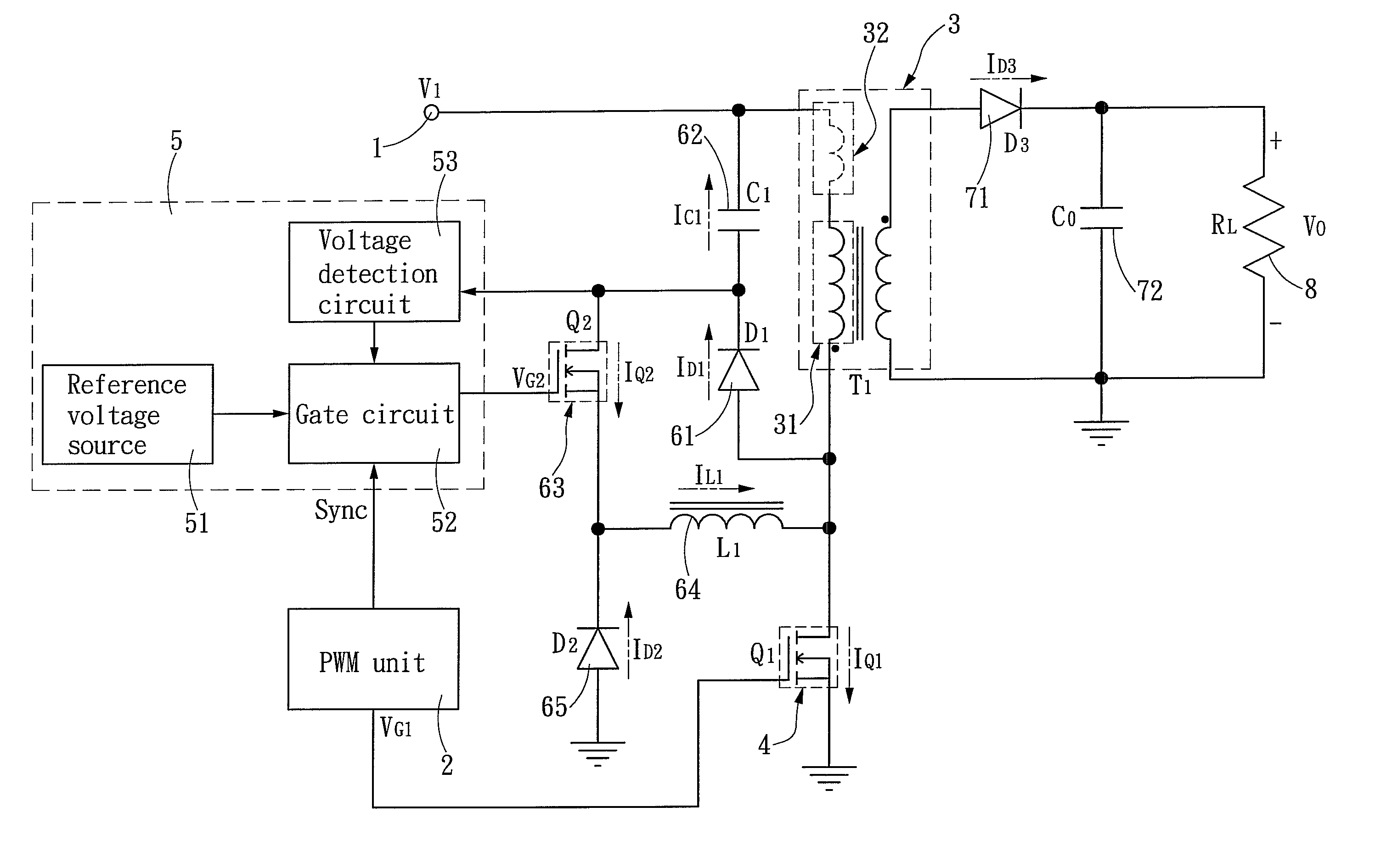
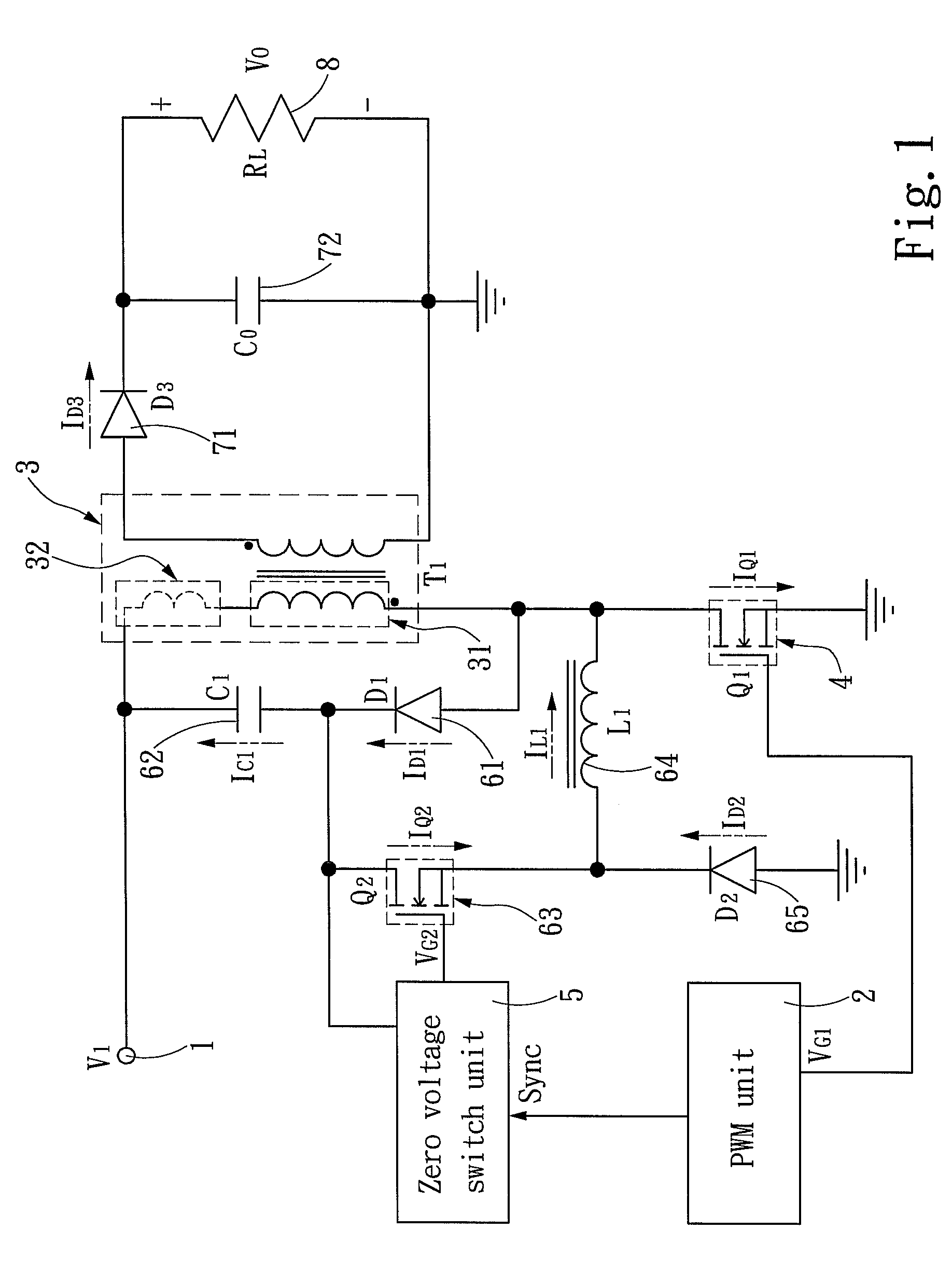
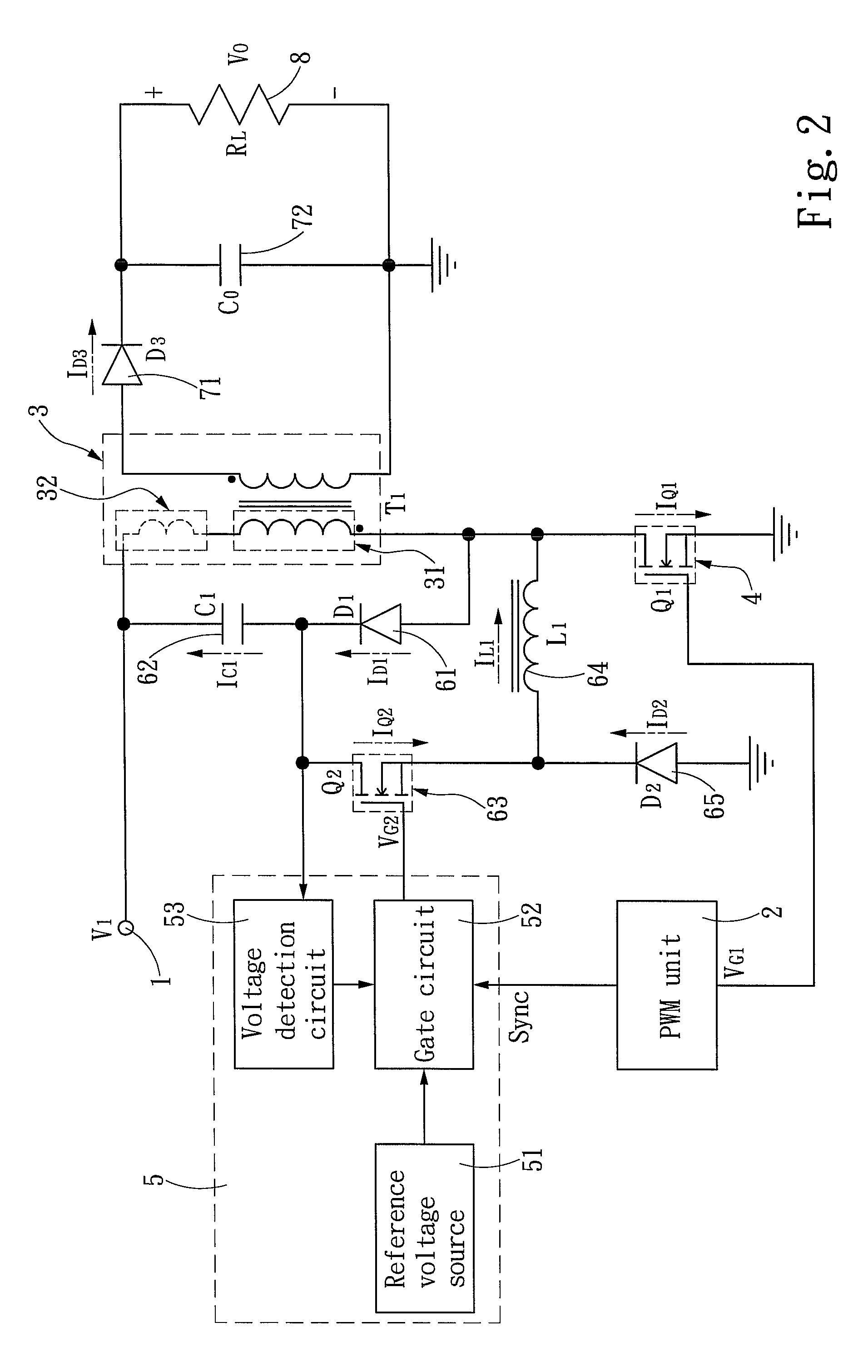
[0009]Please refer to FIG. 1, the invention provides a flyback converter equipped with an active snubber. The flyback converter includes a transformer 3 (T1) which has a primary winding 31 at a first side to receive input power 1 that goes through energy transformation through electromagnetic inductance to be transferred to a secondary side of the transformer 3. The primary winding 31 generates a leakage inductance 32 due to not being fully coupled. A primary switch 4 is provided to connect to the primary winding 31. There is also a pulse-width modulation (PWM) unit 2 to generate a periodic signal VG1 to drive the primary switch 4. The periodic signal includes an ON period and an OFF period to drive the primary switch 4 thereby to control a current period passing through the primary winding 31. The polarities of the secondary side of the transformer 3 and the primary winding 31 are opposite to each other to form a flyback conversion structure. The electric power sent to the secondar...


PUM


Abstract

A flyback converter having an active snubber includes a transformer to receive input power. The transformer has a primary winding at a first side. The active snubber is coupled in parallel with two ends of the primary winding and has a first circumferential circuit coupling in parallel with the primary winding, a second circumferential circuit and a zero voltage switch unit. The second circumferential circuit is controlled by the zero voltage switch unit and incorporated with the first circumferential circuit to form double damping paths to reduce current and prevent resonance that might otherwise occur to a single circumferential circuit and the secondary side of the transformer.

Description

FIELD OF THE INVENTION[0001]The present invention relates to a flyback converter having an active snubber and particularly to a flyback converter equipped with an active snubber to provide electric power damping.BACKGROUND OF THE INVENTION[0002]In power supply (or other electronic devices) switches such as Bipolar Junction Transistors (BJTs), MOSFET and the like are needed. They mainly aim to set current ON or OFF for circuits. As the energy of inductors in the circuits cannot be cut off abruptly, at the switch instant a spike many times of the regular voltage often occurs. When the switches are located in the circuits of a higher electric power, occurrence of the spike could damage the circuit or switches. Snubber is developed to solve this problem. It aims to harness the spike or noise at the switch instant. The snubber usually includes a capacitor and a resistor coupling in parallel with a switch, and a diode is employed to allow current to pass through one way. As there is no ad...

Claims


Application Information

Patent Timeline
Patent Type & Authority Patents(United States)
IPC IPC(8): H02H7/122
CPCH02M1/34H02M3/33507H02M2001/342Y02B70/1491H02M1/342Y02B70/10
Inventor LIN, KUO-FANTSUI, CHIEN-LI
Owner SPI ELECTRONICS
Why Eureka
Try Eureka