
Apparatus for storage and liberation of compressed hydrogen gas in microcylindrical arrays and system for filling the microcylindrical arrays

a technology of compressed hydrogen and microcylindrical arrays, which is applied in the field of fuel storage, can solve the problems of low temperature-induced hydrogen release rate of microcapsules, breakage of microcapsules, and destruction of microcapsules during operation, and achieves low manufacturing cost and durable and reliable construction

Active Publication Date: 2011-01-18
CEN CO LTD +1
View PDF21 Cites 6 Cited by
  • Summary
  • Abstract
  • Description
  • Claims
  • Application Information

AI Technical Summary

Benefits of technology

The apparatus enables efficient and safe storage and liberation of hydrogen, maintaining microcapsule integrity and allowing for repeated use, while also being adaptable for other gases, thus improving safety and reducing costs.

Problems solved by technology

One of the problems associated with liberation of compressed hydrogen by diffusion is associated with a relatively low rate of temperature induced hydrogen release from the microcapsules.
Both these factors may cause breakage of the microcapsules.
On the other hand, when the liberation of compressed hydrogen from the microcapsules is carried out with a mechanical opener, the microcapsules are destroyed during operation.

Method used


Image

  • Apparatus for storage and liberation of compressed hydrogen gas in microcylindrical arrays and system for filling the microcylindrical arrays
  • Apparatus for storage and liberation of compressed hydrogen gas in microcylindrical arrays and system for filling the microcylindrical arrays
  • Apparatus for storage and liberation of compressed hydrogen gas in microcylindrical arrays and system for filling the microcylindrical arrays

Examples


Embodiment Construction

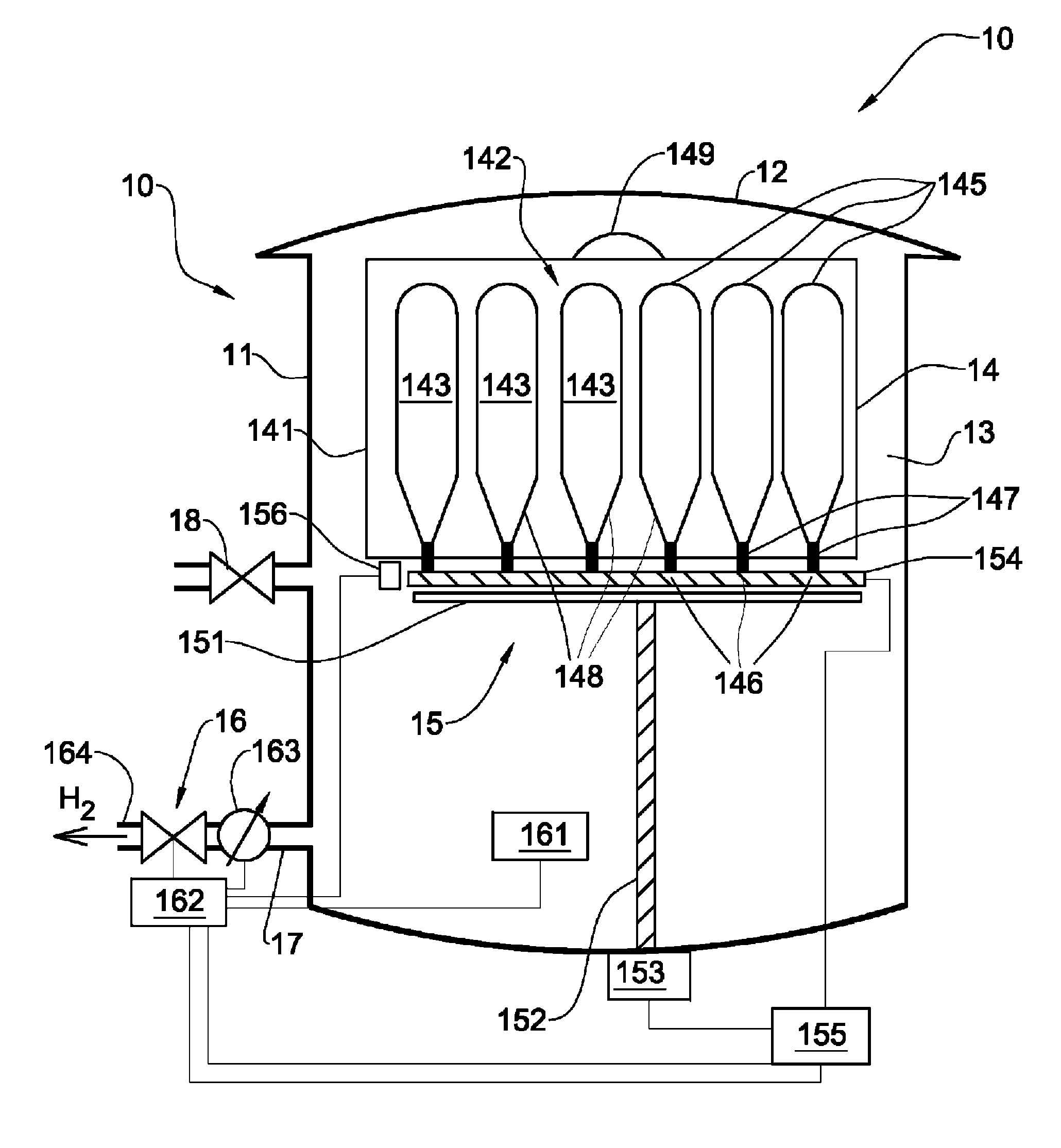
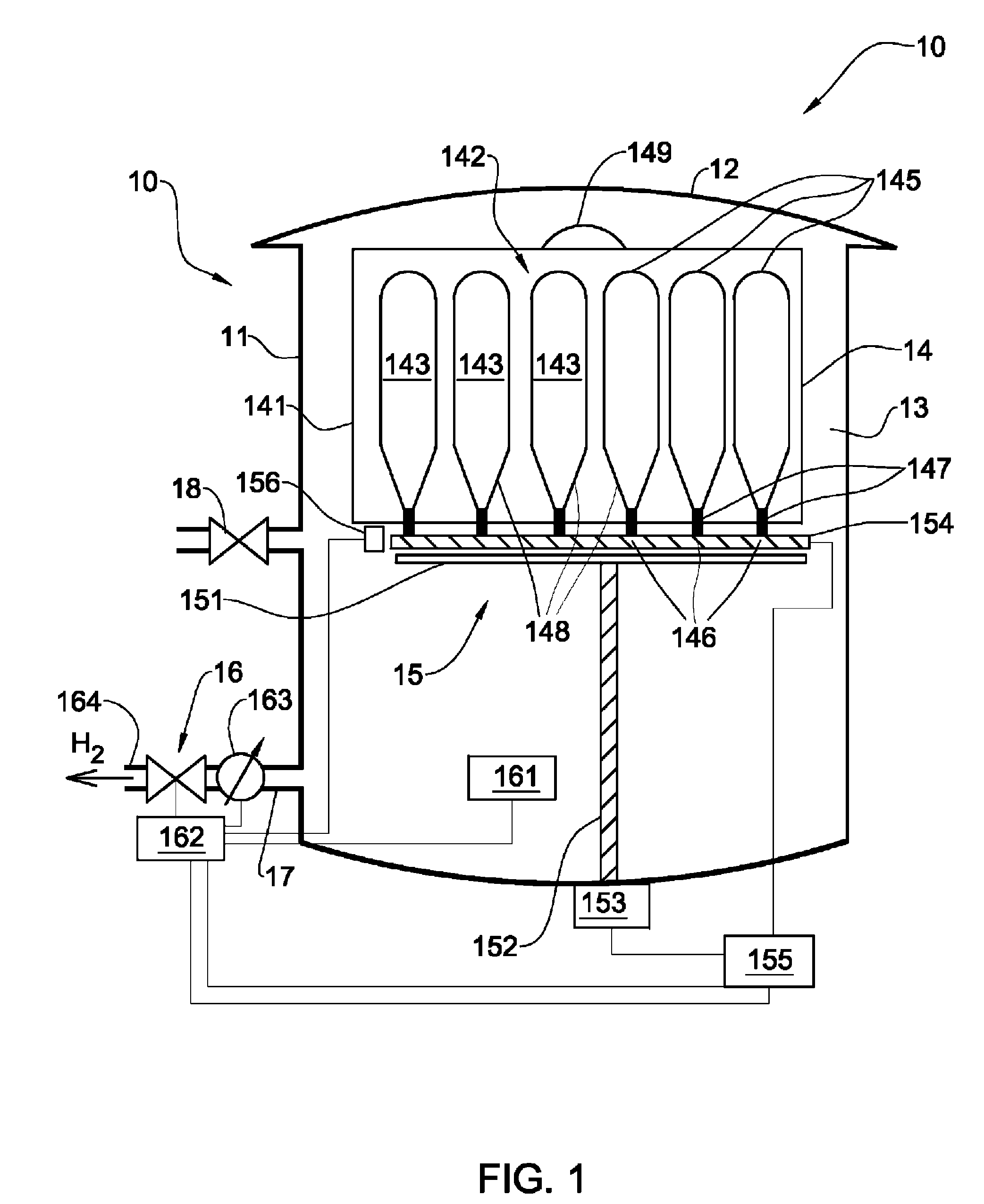
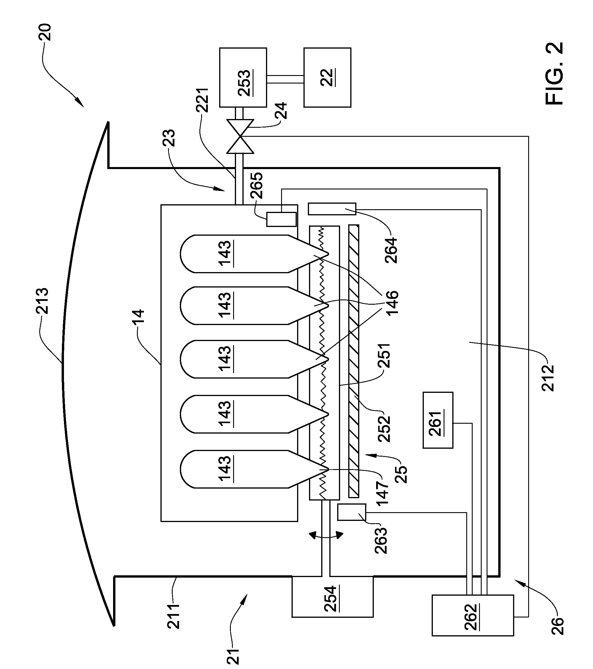
The principles and operation of an apparatus for storage hydrogen gas according to the present invention may be better understood with reference to the drawings and the accompanying description. It should be understood that these drawings are given for illustrative purposes only and are not meant to be limiting. It should be noted that the figures illustrating various examples of the apparatus of the present invention are not to scale, and are not in proportion, for purposes of clarity. It should be noted that the blocks as well other elements in these figures are intended as functional entities only, such that the functional relationships between the entities are shown, rather than any physical connections and / or physical relationships. The same reference numerals and alphabetic characters will be utilized for identifying those components which are common in the hydrogen storage apparatus and its components shown in the drawings throughout the present description of the invention.

R...


PUM

PropertyMeasurementUnit
pressuresaaaaaaaaaa
activation energyaaaaaaaaaa
external diameteraaaaaaaaaa

Abstract

An apparatus for storage and liberation of compressed hydrogen or other gases is provided. The apparatus includes a housing defining a chamber that includes a cartridge comprising an array of hollow microcylinders defining cavities for storage compressed gas. Each microcylinder has at least one end sealed with a plug made of an easily meltable alloy. The apparatus also includes a gas liberating tool configured for controllable liberating the gas from the cartridge into the chamber; and a control system operatively coupled to the discharge valve and liberating tool, and configured for controlling operation thereof. According to another aspect of the invention, there are provided a system and method for filling a cartridge having an array of hollow microcylinders having open ends. The filling includes placing the cartridge into a chamber of an autoclave, and compressing the gas in the chamber, thereby providing permeation of the gas through the open ends into cavities of the microcylinders. Thereafter, the open ends are sealed with plugs made of an easily meltable alloy.

Description

FIELD OF THE INVENTIONThe present invention relates generally to fuel storage, and in particular, to accumulation, storage and liberation of gases.BACKGROUND OF THE INVENTIONIt is well-known that hydrogen is a very high energy density element and clean-burning fuel. Hydrogen can be combined with oxygen through combustion, or through a fuel cell mediated oxidation / reduction reactions, to produce heat, or electrical power. The primary product of this reaction is water, which is non-polluting and can be recycled to regenerate hydrogen and oxygen.Currently, hydrogen energetics is the focus of interest in nuclear industry, motor transport, auto industry, chemical industry, aerospace industry, etc. In particular, the transport sector is a consumer of about half of the world's crude oil production. Moreover, in large metropolitan agglomerations worldwide, road traffic represents one of the most important and fastest growing emission sources for both pollutants and noise. Hydrogen as a new ...

Claims


Application Information

Patent Timeline
Patent Type & Authority Patents(United States)
IPC IPC(8): F17C1/00B65D85/00B67D7/78
CPCF17C1/14F17C5/06F17C7/00F17C13/025F17C13/026F17C1/16Y02E60/324F17C2201/0109F17C2201/0128F17C2201/0157F17C2201/032F17C2201/056F17C2201/058F17C2203/015F17C2203/0617F17C2203/0629F17C2203/0636F17C2203/0658F17C2203/066F17C2203/0663F17C2203/0673F17C2203/0697F17C2205/0115F17C2205/0142F17C2205/0149F17C2205/0165F17C2205/0302F17C2205/0317F17C2205/0326F17C2205/0332F17C2221/011F17C2221/012F17C2221/033F17C2223/0123F17C2223/035F17C2223/036F17C2225/0123F17C2225/036F17C2227/046F17C2250/036F17C2250/043F17C2250/0439F17C2250/0443F17C2250/0491F17C2250/0626F17C2250/0631F17C2250/0636F17C2260/01F17C2270/0168F17C2270/0184F17C2270/0186F17C2270/05F17C2270/0736Y02E60/321Y02E60/32F17C13/00F17C13/04
Inventor ZHEVAGO, NIKOLAYDENISOV, EMIL
Owner CEN CO LTD
Learn More