Micro fuel cell

a fuel cell and micro-chip technology, applied in the field of micro-fabricated thin films and single-chamber solid oxide fuel cells, can solve the problems of high cost of production of devices and their overall efficiency still not meeting the standards of practical us

Inactive Publication Date: 2011-01-18
MASSACHUSETTS INST OF TECH
View PDF34 Cites 19 Cited by
  • Summary
  • Abstract
  • Description
  • Claims
  • Application Information

AI Technical Summary

Problems solved by technology

However, production of the devices can be costly and their overall efficiency still does not meet the standards for practical use.

Method used


Image

  • Micro fuel cell
  • Micro fuel cell
  • Micro fuel cell

Examples


Embodiment Construction

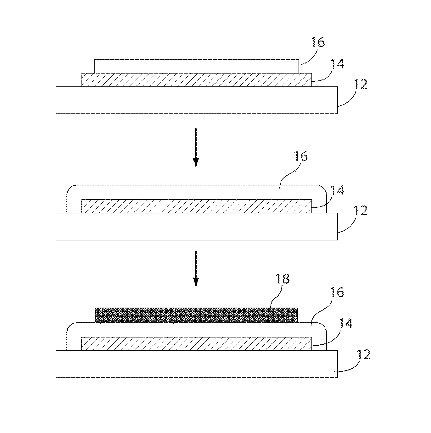
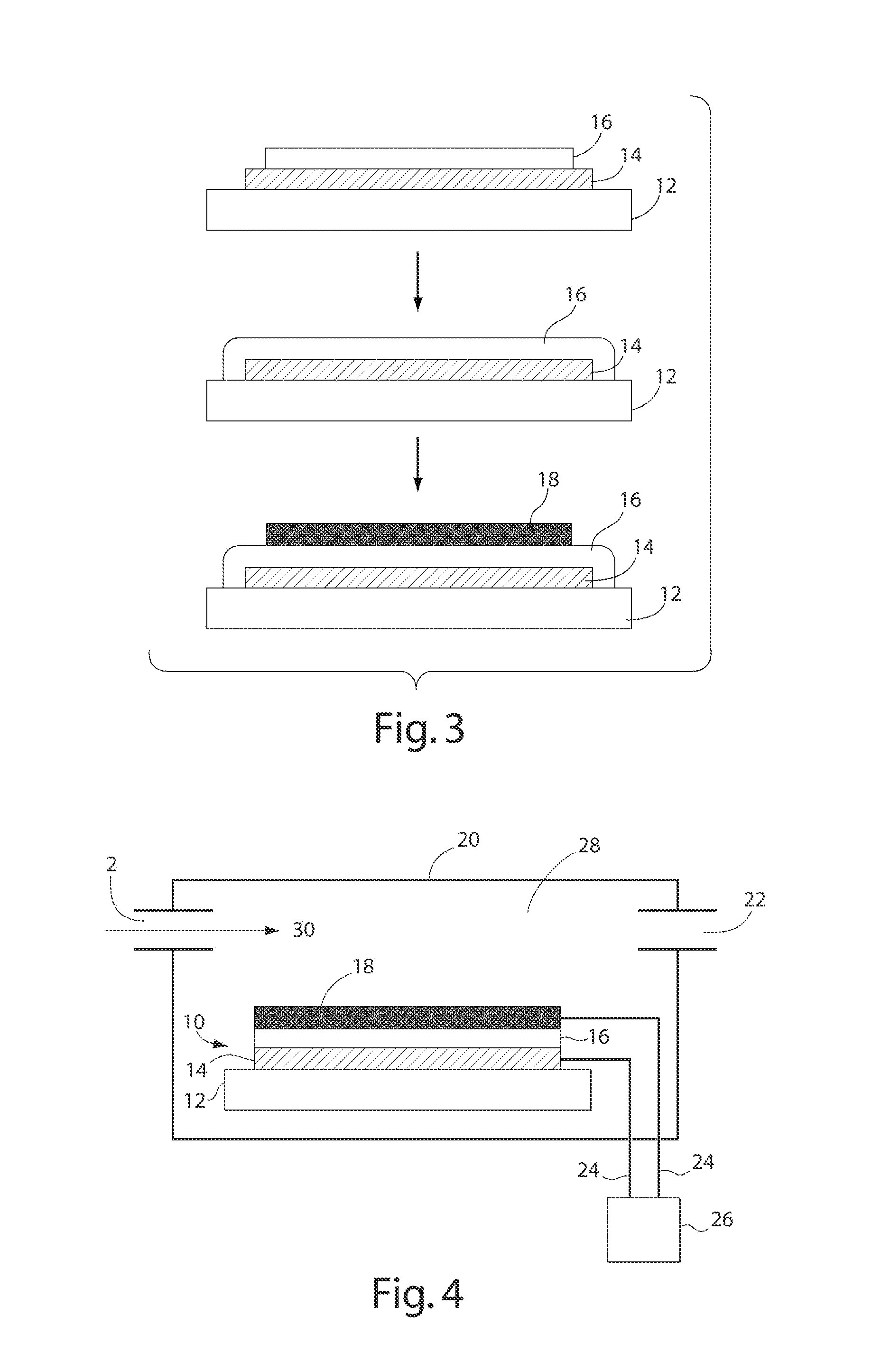
[0019]The present invention relates to thin-film, single chamber solid oxide fuel cells and methods for their use and fabrication. One of the chief impediments to practical and efficient SOFC operation is a requirement for high operating temperatures (approximately 800-1000° C.). Prolonged use at high operating temperatures requires that the materials of construction possess adequate chemical and structural stability to sustain high temperatures without chemical degradation of the materials, as well as similar thermal expansion coefficients, to minimize thermal stresses that may lead to cracking and / or delamination. In one aspect, the invention provides a method for making a fuel cell using “thin-film” technology. A thin film can be formed using processes such as spin-on methods, chemical vapor deposition, pulsed laser deposition, vacuum plasma spray, wet spray, sputtering, evaporation, or molecular beam epitaxy. The use of thin-film processing may allow for the reduction of the act...


PUM

PropertyMeasurementUnit
thicknessaaaaaaaaaa
operating temperaturesaaaaaaaaaa
temperaturesaaaaaaaaaa

Abstract

The present invention discloses a solid oxide fuel cell and method for fabricating solid oxide fuel cells using thin film processing techniques. The fuel cell comprises a cathode layer, an electrolyte layer, and an anode layer arranged in various configurations to optimize fuel cell performance.

Description

RELATED APPLICATIONS[0001]This application claims priority under 35 U.S.C. §119(e) to U.S. Provisional Application Ser. No. 60 / 710,795, entitled “MICRO FUEL CELL,” filed on Aug. 23, 2005, which is herein incorporated by reference in its entirety.GOVERNMENT SPONSORSHIP[0002]This invention was sponsored by the Army Research Office Grant No. DAAD-01-1-0566. The government has certain rights in the invention.FIELD OF THE INVENTION[0003]The present invention relates to fuel cells and particularly to microfabricated thin-film, single chamber solid oxide fuel cells, and methods for their fabrication.BACKGROUND OF THE INTENTION[0004]A fuel cell is an electrochemical device that can produce electricity by combining a fuel (such as hydrogen or a hydrocarbon) and an oxidant (such as pure oxygen or air) to produce electricity. Fuel cells typically include two electrodes (i.e., an anode and a cathode) that are in contact with a common electrolyte. A solid oxide fuel cell (SOFC) includes a solid-...

Claims


Application Information

Patent Timeline
Patent Type & Authority Patents(United States)
IPC IPC(8): H01M4/86H01M8/10B05D5/12
CPCH01M4/8621H01M4/8885H01M8/1213H01M8/1226H01M8/1246H01M8/1286H01M4/9033H01M8/126H01M2008/1293Y02E60/521Y02E60/525Y02E60/50Y02P70/50
Inventor HERTZ, JOSHUA L.TULLER, HARRY L.
Owner MASSACHUSETTS INST OF TECH
Why Eureka
Try Eureka