Supercharge Your Innovation With Domain-Expert AI Agents!

Radiant heat barrier

a radiation-proof, heat-insulating technology, applied in heat-insulating, building roofs, roofing, etc., can solve the problem of little to prevent heat transfer due to radiation

Inactive Publication Date: 2011-01-25
SNYDER NAT CORP
View PDF49 Cites 8 Cited by
  • Summary
  • Abstract
  • Description
  • Claims
  • Application Information

AI Technical Summary

Benefits of technology

"The invention provides a radiant heat barrier that can be installed under various roofs to reduce heat loss and improve energy efficiency. The barrier consists of boards that can be erected into trays that fit between the roof supports. The boards have a high-reflectivity, low-emissivity surface that reflects most of the radiation energy back in the direction from where it originated. The trays have end walls to trap air between the rafters. The invention also provides a method for installing the trays and a roof configuration with the barrier. Additionally, the invention provides a system that combines the barrier with traditional bulk insulation and an optional catwalk for installation. The invention also provides a plurality of clips to connect the channels in an end-to-end configuration. The insulation kit includes a plurality of channel boards, risers, and platforms."

Problems solved by technology

Although this insulation is effective to container heat transfer by conduction and convection, it does little to prevent heat transfer due to radiation.

Method used


Image

  • Radiant heat barrier
  • Radiant heat barrier
  • Radiant heat barrier

Examples


Embodiment Construction

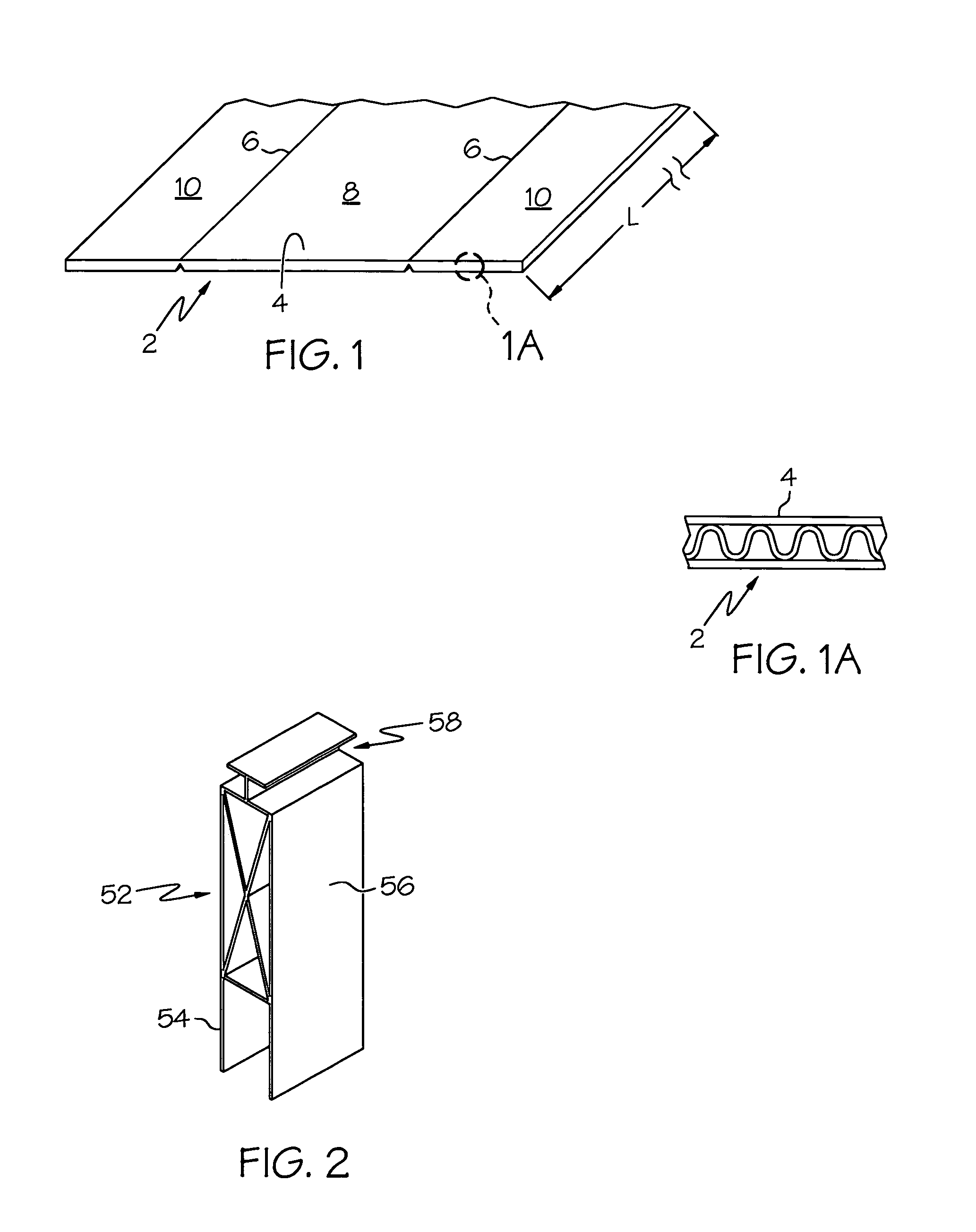
[0034]A channel board is indicated generally by the numeral 2 in FIG. 1. Board 2 includes a corrugated central layer sandwiched between a pair of liner boards. At least one of the liner boards has an outwardly-disposed, high-reflectivity, low-emissivity surface 4. Such a surface may be formed by laminating a thin layer of metal such as aluminum to a liner board. The surface may also be formed by coating the liner board with a high-reflectivity, low-emissivity material such as an appropriate paint or by metallizing the liner board. Both outer surfaces of board 2 may be high-reflectivity, low-emissivity. Board 2 may be treated to be fire resistant or fire proof. An example of a board structure that may be used as channel board 2 is disclosed in U.S. Pat. No. 5,339,577; the disclosure of which are incorporated herein by reference. In some applications, board 2 may be perforated to allow moisture to pass through board 2 so that such moisture is not trapped in the building.

[0035]Channel ...


PUM


Abstract

A radiant heat barrier may be installed under a wide variety of roofs between the roof supports. In one configuration, the radiant heat barrier is provided in the form of a plurality of boards that are each erectable into a barrier tray having at least one high-reflectivity, low-emissivity surface. The surface reflects a large percentage of the radiation energy back in the direction from where the radiation originated. Each board includes features that allow the board to be formed into different-sized trays. In one configuration, the trays may be configured to fit between the rafters of typical residential construction. The trays include tabs that allow the tray to be mounted to the supports.

Description

CROSS REFERENCE TO RELATED APPLICATIONS[0001]This application claims the benefit of U.S. Provisional Patent Application Ser. No. 60 / 853,237, filed Oct. 20, 2006, and claims the benefit of U.S. Provisional Patent Application Ser. No. 60 / 873,754, filed Dec. 8, 2006; the disclosures of both are incorporated herein by reference.BACKGROUND OF THE INVENTION[0002]1. Technical Field[0003]The present invention generally relates to insulation for buildings and, more particularly, to insulation members designed to reflect radiant heat energy. The radiant barrier may be used with or without traditional bulk insulation. The insulation members are provided in the form of corrugated boards having at least one reflective surface. The boards may be formed into five-sided trays that limit air flow and reflect radiant energy or may be formed into channels that fit over bulk insulation.[0004]2. Background Information[0005]A variety of building, both commercial and residential, would benefit from a radi...

Claims


Application Information

Patent Timeline
Patent Type & Authority Patents(United States)
IPC IPC(8): E04B1/78
CPCE04D13/1625
Inventor SNYDER, DARRYL L.
Owner SNYDER NAT CORP
Features
  • R&D
  • Intellectual Property
  • Life Sciences
  • Materials
  • Tech Scout
  • Unparalleled Data Quality
  • Higher Quality Content
  • 60% Fewer Hallucinations
Learn More