Hydraulic system with compensation for kinematic position changes of machine members

a hydraulic system and compensation technology, applied in the direction of fluid couplings, servomotors, couplings, etc., can solve the problems of reducing machine performance, affecting the instantaneous bandwidth of the associated actuators, and limited maximum acceleration that can be controlled, so as to enhance the operation efficiency of the hydraulic system

Inactive Publication Date: 2011-01-25
HUSCO INT INC
View PDF8 Cites 12 Cited by
  • Summary
  • Abstract
  • Description
  • Claims
  • Application Information

AI Technical Summary

Benefits of technology

[0015]It has been realized by the present inventor that the operating efficiency of a hydraulic system can be enhanced by taking into account an estimate of the kinematic position of the various machine components and use the position estimates to determine the load that those components place on the hydraulic system.

Problems solved by technology

The greater the inertia, the higher the hydraulic force required to accelerate the function to a command velocity and thus the maximum acceleration that can be controlled is limited.
In addition the ability of the hydraulics to apply torque to this inertia changes with the position of the structures and also affects the instantaneous bandwidth of the associated actuators.
For example, attempting to operate the hydraulic actuator faster than it is able to respond, produces jerky motion of the associated machine component, however commanding the hydraulic actuator to operate slower than it is able, unnecessarily diminishes machine performance.
Inevitably, the variable component positions, loads, and environmental constraints require tradeoffs to be made and such tradeoffs often involve adding extra losses (damping) to the hydraulic system to ensure that the machine operates in a stable and predictable manner.
Little work has been done to date to migrate some of the previous tradeoffs that were necessary.
A missing part of the transition to electrohydraulic systems is not recognizing the capability of electronics and software to integrate velocity commands to create position indications for use in machine control.
Although some machines today use position feedback from sensors for position or angle control, such as bucket leveling, these systems only modulate high level commands to the hydraulic functions based on a combination of such feedback signals and operator commands.

Method used


Image

  • Hydraulic system with compensation for kinematic position changes of machine members
  • Hydraulic system with compensation for kinematic position changes of machine members
  • Hydraulic system with compensation for kinematic position changes of machine members

Examples


Embodiment Construction

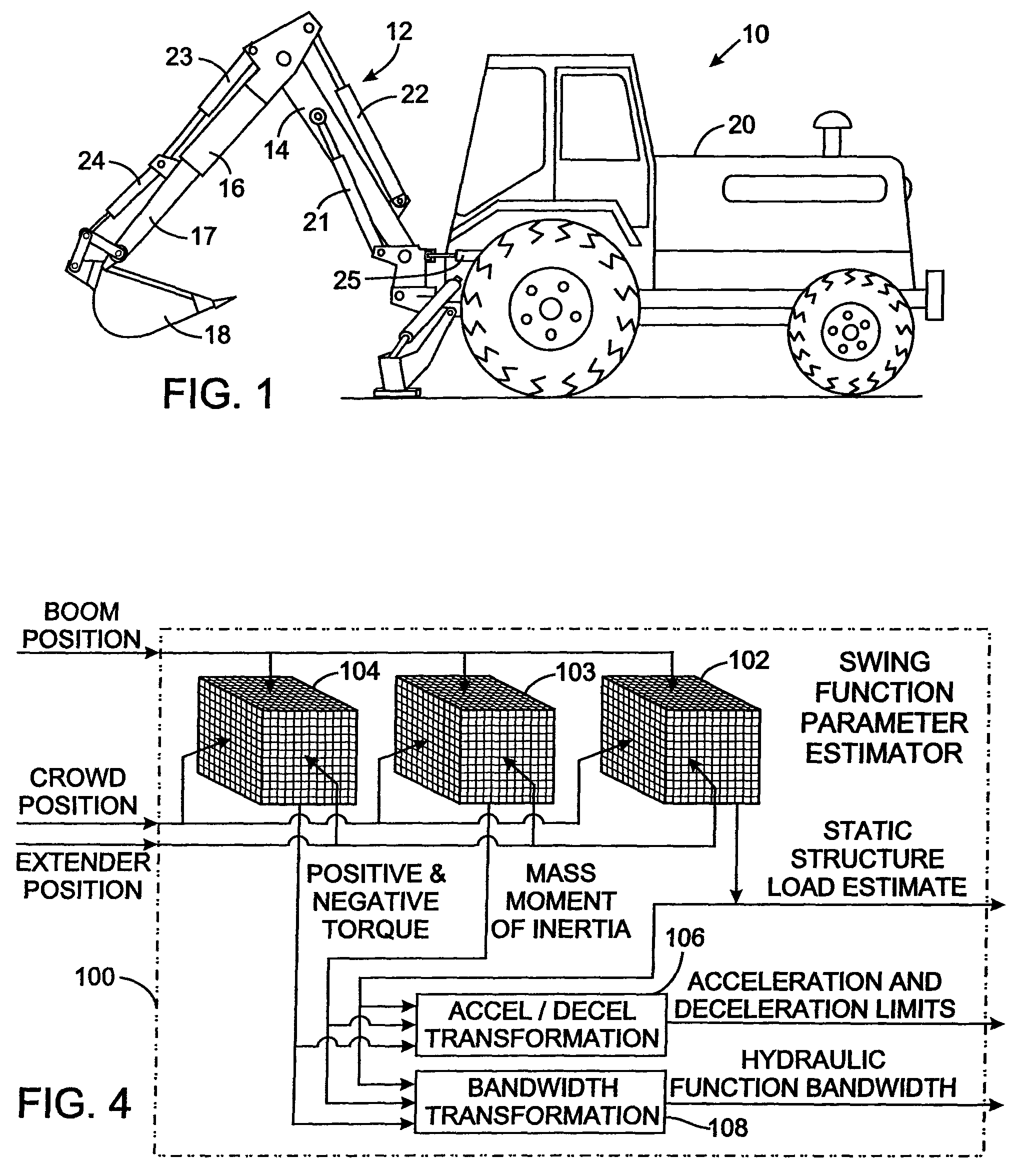
[0025]With initial reference to FIG. 1, a backhoe 10 has a hydraulically powered work apparatus 12, commonly known as a boom assembly, that comprises a boom 14, arm 16, an extender 17, and a bucket 18. The bucket 18 can be replaced by another type of implement. Operations performed by work apparatus 12 include, for example, lifting, lowering, and otherwise moving a load carried in the bucket. The boom 14 has one end pivotally mounted to the backhoe tractor 20 and is raised and lowered by a first, or boom, hydraulic actuator 21. The arm 16 connected to pivot at the opposite end of the boom 14 under force applied by a second, or arm, hydraulic actuator 22. The extender 17 is telescopically extended from and retracted into the arm 16 by a third hydraulic actuator 23, also called an extender actuator. A fourth, or bucket, actuator 24 pivots the bucket 18 that is attached at the remote end of the extender 17. A fifth hydraulic actuator 25 swings the work apparatus 12 with respect to the ...


PUM


Abstract

A machine, such as a backhoe, has a series of components connected in series and moved by separate hydraulic actuators. A position estimator determines the present position of each component from the load acting on the associated hydraulic actuator and a velocity command for the component. For each component, a function parameter estimator uses the present positions of the components to derive a set of parameters that include a static structure load that the components exert on the associated hydraulic actuator, acceleration and deceleration limits for both directions of component motion, and a control bandwidth for the associated hydraulic actuator. The set of parameters for a given component is used to control the associated hydraulic actuator.

Description

CROSS-REFERENCE TO RELATED APPLICATIONS[0001]Not ApplicableSTATEMENT REGARDING FEDERALLY SPONSORED RESEARCH OR DEVELOPMENT[0002]Not ApplicableBACKGROUND OF THE INVENTION[0003]1. Field of the Invention[0004]The present invention relates to a hydraulic system for operating components of a machine, and more particularly to such systems for machines, such as a backhoe with a boom assembly for example, in which the hydraulic load varies as a function of the position of the components being operated.[0005]2. Description of the Related Art[0006]A wide variety of machines have moveable members which are driven by a hydraulic actuator, such as a cylinder-piston arrangement or a hydraulic motor. For example, a backhoe has a tractor on which is mounted an assembly comprising a boom, an arm, an extender, and a bucket connected in series, with each of those components being driven by one or more cylinder-piston arrangement. That assembly swings left and right with respect to the tractor when dri...

Claims


Application Information

Patent Timeline
Patent Type & Authority Patents(United States)
IPC IPC(8): F15B11/00E02F9/22
CPCE02F9/2203E02F9/2221F15B21/087F15B2211/6309F15B2211/6313F15B2211/6336F15B2211/6346
Inventor PFAFF, JOSEPH L.
Owner HUSCO INT INC
Why Eureka
Try Eureka