
Optical fiber temperature distribution measuring apparatus, method for measuring optical fiber temperature distribution, and optical fiber temperature distribution measuring system

a temperature distribution and measuring apparatus technology, applied in the direction of heat measurement, optical radiation measurement, instruments, etc., can solve the problems of significant increase in error and inability to obtain correct temperature information, and achieve the effect of accurate temperatur

Active Publication Date: 2011-01-25
SUMITOMO ELECTRIC IND LTD
View PDF8 Cites 6 Cited by
  • Summary
  • Abstract
  • Description
  • Claims
  • Application Information

AI Technical Summary

Benefits of technology

Enables precise temperature measurement by accounting for hydrogen-induced optical transmission losses, thereby reducing errors and ensuring accurate temperature readings in hydrogen atmospheres.

Problems solved by technology

However, according to the conventional method for measuring optical fiber temperature distribution, there is a following disadvantage. FIG. 14A shows the principle for measuring the optical fiber in the conventional art, in that when the optical fiber 2 to be measured is in a hydrogen atmosphere (i.e. hydrogen is contained in a ambient atmosphere 30) for an actual measurement, hydrogen molecules are diffused into the optical fiber 2 to be measured.
As a result, correct temperature information cannot be obtained.
This error is significantly increased in accordance with the increase in the distance of the optical fiber to be measured and the increase in the hydrogen partial pressure, respectively.

Method used


Image

  • Optical fiber temperature distribution measuring apparatus, method for measuring optical fiber temperature distribution, and optical fiber temperature distribution measuring system
  • Optical fiber temperature distribution measuring apparatus, method for measuring optical fiber temperature distribution, and optical fiber temperature distribution measuring system
  • Optical fiber temperature distribution measuring apparatus, method for measuring optical fiber temperature distribution, and optical fiber temperature distribution measuring system

Examples


first preferred embodiment

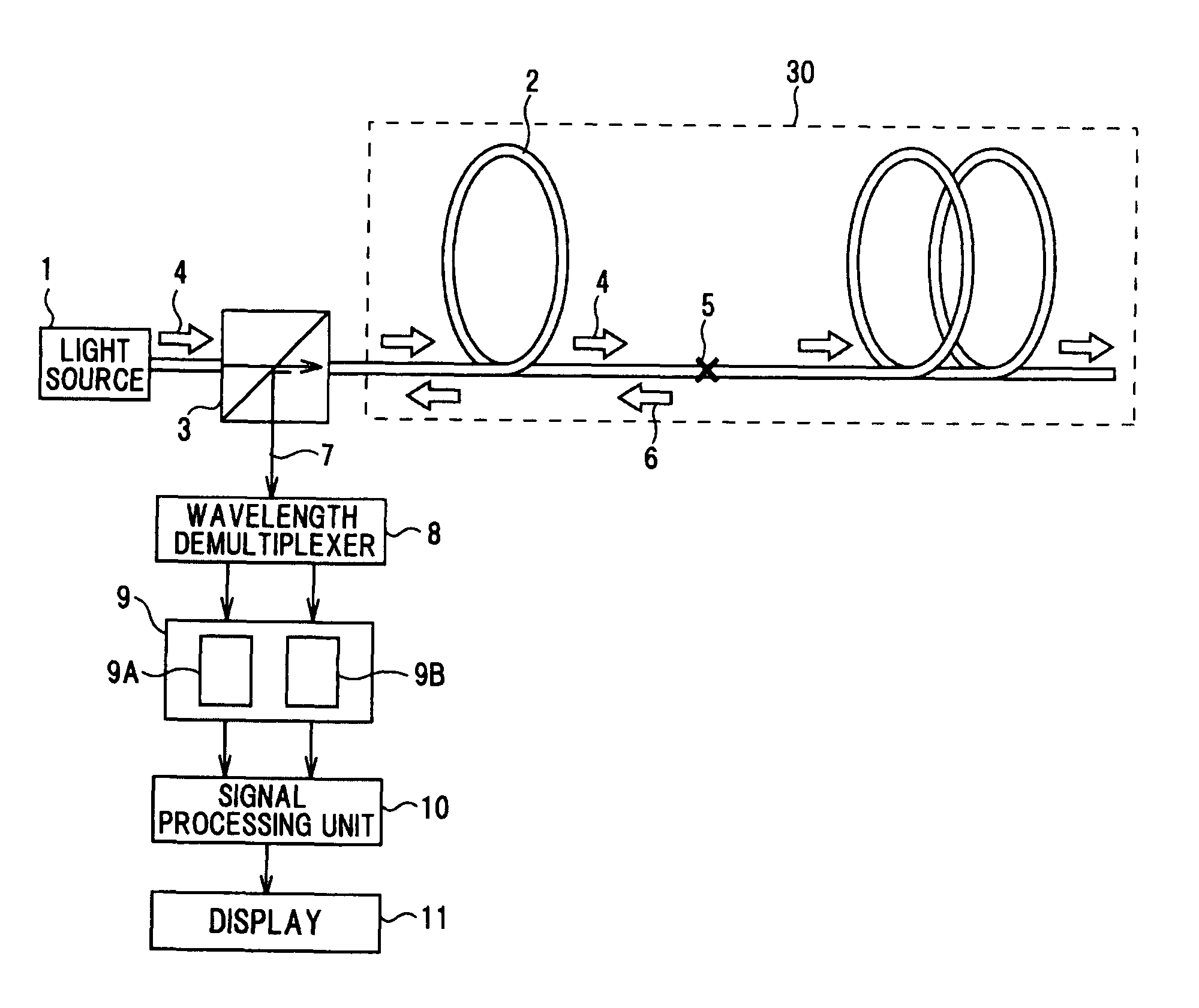
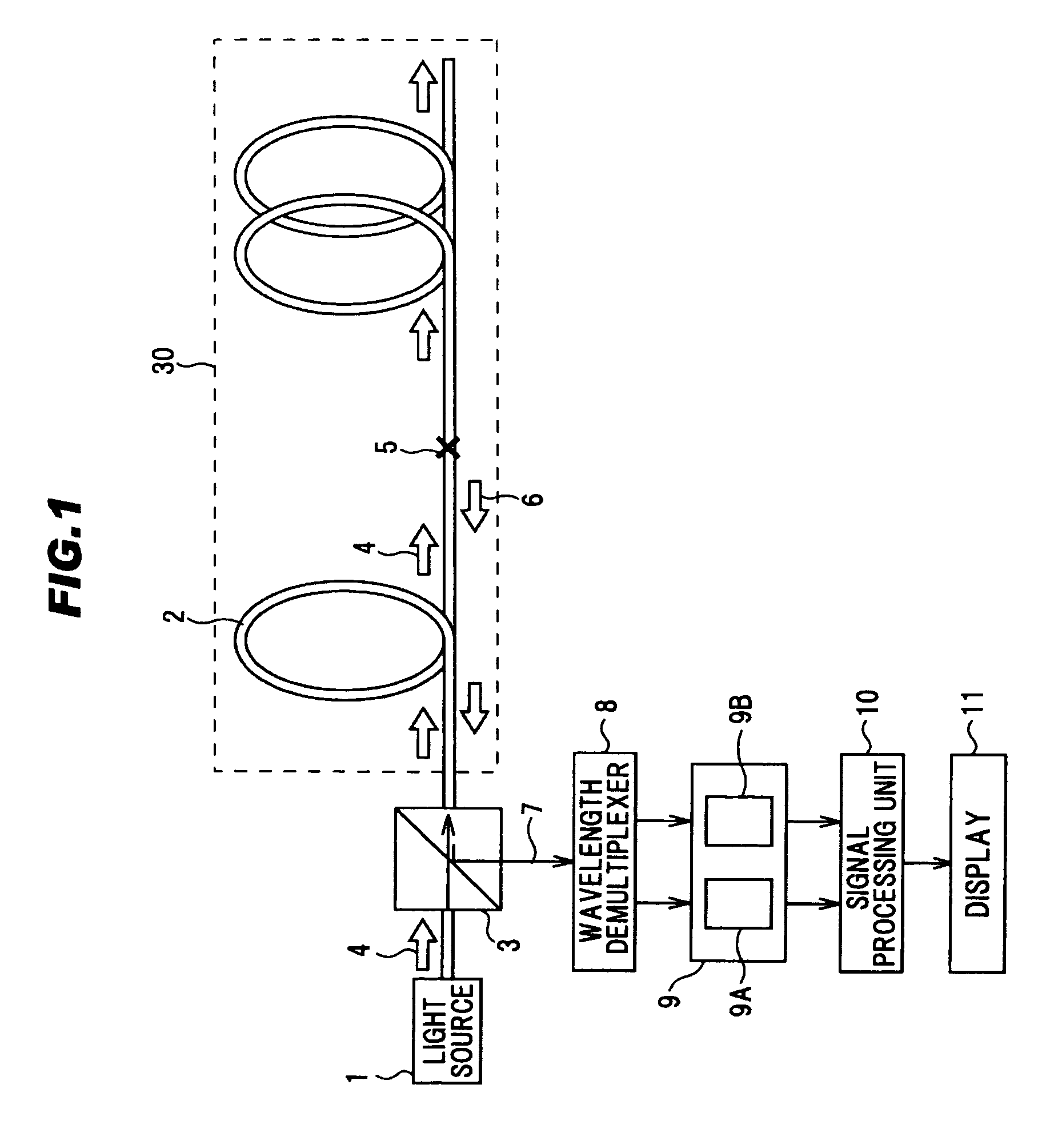
[0143]FIG. 1 is a schematic block-diagram showing an optical fiber temperature distribution measuring system in a first preferred embodiment according to the invention. This optical fiber temperature distribution measuring system comprises a light source 1, an optical fiber 2 to be measured, a beam splitter 3 for inputting an input pulse light 4 to the optical fiber 2 to be measured, changing an optical path of a backscattering light 6 generated at a scattering point 5 of the optical fiber 2 to be measured, and outputting the backscattering light 6 as an output light 7 to a wavelength demultiplexer 8, the wavelength demultiplexer 8 for separating the output light of the beam splitter 3 into a Stokes light and an anti-Stokes light, a signal detecting unit 9 comprising a Stokes light detecting part 9A for detecting the Stokes light separated by the wavelength demultiplexer 8, and an anti-Stokes light detecting part 9B for detecting the Stokes light separated by the wavelength demultip...

second preferred embodiment

[0162]FIG. 6 is a schematic block-diagram showing an optical fiber temperature distribution measuring apparatus in a second preferred embodiment according to the invention. The second preferred embodiment differs from the first preferred embodiment, in that the configuration comprises a wavelength demultiplexer 8 for separating the light output from the beam splitter 3 into a Stokes light, an anti-Stokes light, and a Rayleigh light, and a signal detecting unit 9 comprising a Stokes light detecting part 9A for detecting the Stokes light separated by the wavelength demultiplexer 8, an anti-Stokes light detecting part 9B for detecting the anti-Stokes light separated by the wavelength demultiplexer 8, and a Rayleigh light detecting part 9C for detecting the Rayleigh light separated by the wavelength demultiplexer 8. FIG. 6 also shows a state where the optical fiber 2 to be measured is in the hydrogen atmosphere. In addition, common reference numerals are assigned to parts having the sam...

third preferred embodiment

[0184]FIG. 10 is a schematic block-diagram showing an optical fiber temperature distribution measuring system in a third preferred embodiment according to the invention. In the third preferred embodiment, a light with a wavelength λr that is different from the wavelength λ of a temperature measuring light is used as a reference light for measuring a variation of the received light intensity. In the concrete, as shown in FIG. 18A, a light with a wavelength of 1240 nm is used as the reference light, since an increase in the optical transmission loss due to the hydrogen molecules remarkably appears at the wavelength of 1240 nm. The third preferred embodiment differs from the first preferred embodiment, in that the configuration comprises a 1240 nm light source 1A for inputting a light with a wavelength of 1240 nm to the optical fiber 2 to be measured via the beam splitter 3, a temperature measuring light source 1B, a wavelength demultiplexer 8 for separating the light output from the b...


PUM

PropertyMeasurementUnit
refractive indexaaaaaaaaaa

Abstract

An optical fiber temperature distribution measuring apparatus and a method for measuring optical fiber temperature distribution, provided with a light source for inputting a pulse light to an optical fiber to be measured, a signal detecting unit for detecting a received light intensity of a predetermined light included in a backscattering light generated by an input of the pulse light in the optical fiber to be measured, and a signal processing unit for calculating a value corresponding to a variation of the received light intensity due to a hydrogen molecular absorption of the optical fiber to be measured based on the received light intensity of the predetermined light, to compensate the received light intensity of the predetermined light corresponding to a temperature of the optical fiber to be measured based on the value.

Description

BACKGROUND OF THE INVENTION[0001]1. Field of the Invention[0002]The present invention relates to an optical fiber temperature distribution measuring apparatus, a method for measuring optical fiber temperature distribution, and an optical fiber temperature distribution measuring system, that are for optical and remote measurement of a temperature distribution in an optical fiber.[0003]The present application is based on International Patent Application No. PCT / JP2006 / 318858 the entire contents of which are incorporated herein by reference.[0004]2. Related Art[0005]As a method for measuring optical fiber temperature distribution for optical and remote measurement of a temperature distribution in an optical fiber, a method in which a principle of distance measuring using an OTDR (Optical Time Domain Reflectometry) is combined with a principle of thermometry by detecting a Raman scattering light is known (please see, for example, patent document 1 and non-patent document 1).[0006]FIGS. ...

Claims


Application Information

Patent Timeline
Patent Type & Authority Patents(United States)
IPC IPC(8): G01K11/00G01K15/00G01J5/00G01K1/00
CPCG01K11/32G01K2011/324G01K11/324
Inventor KOMEDA, HIDEHIKOIGI, TSUYOSHIKOYANO, YASUSHIOHKUBO, FUMIYOSHINEGISHI, KAZUAKI
Owner SUMITOMO ELECTRIC IND LTD
Learn More