Posterior stabilized knee prosthesis

Active Publication Date: 2011-01-25
NEW YORK SOC FOR THE RUPTURED & CRIPPLED MAINTAINING THE HOSPITAL FOR SPECIAL SURGERY
View PDF10 Cites 52 Cited by
  • Summary
  • Abstract
  • Description
  • Claims
  • Application Information

AI Technical Summary

Benefits of technology

By modifying the anterior cam surface of the femoral component and by modifying the anterior face of the stabilizing post of the tibial insert, a reduc

Problems solved by technology

However, there are a number of disadvantages with the geometries of conventional posterior cruciate substituting knee designs.
In particular, one common complaint among knee surgeons is that posterior cruciate substituting knee replacements remove too much bone.
Excessive bone removal can lead to intraoperative intercondylar fractures due to the stress concentration created by cutting out bone to accommodate the box of the design.
Bone removal is also not de

Method used


Image

  • Posterior stabilized knee prosthesis
  • Posterior stabilized knee prosthesis
  • Posterior stabilized knee prosthesis

Examples


example

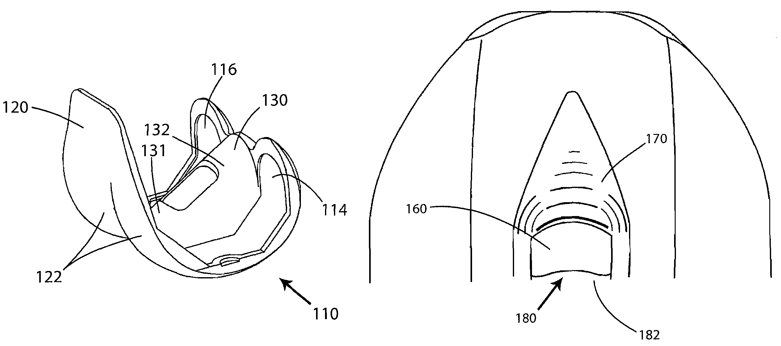
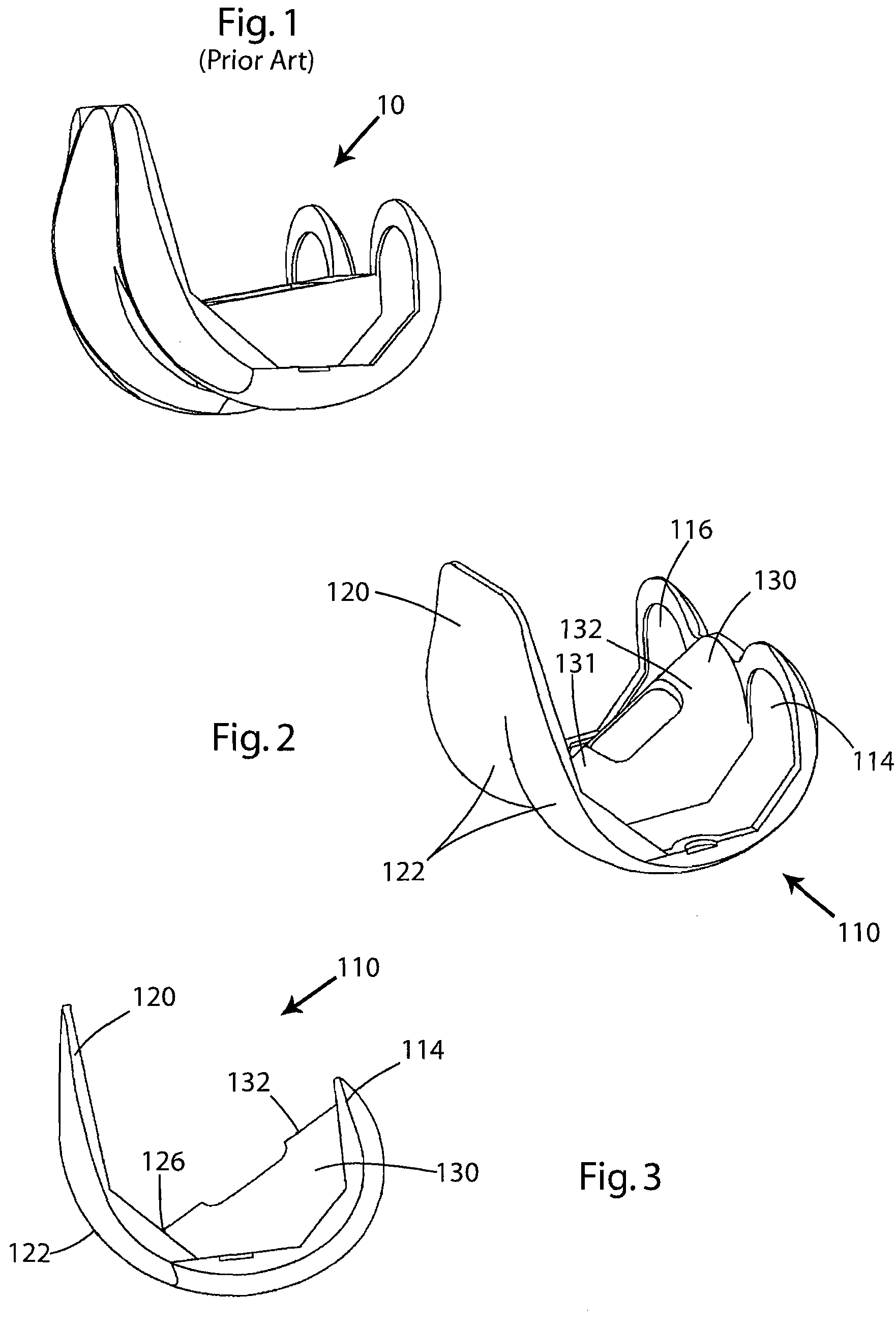
Computer models of the conventional implant of FIG. 1 (i.e., the Exactech Optetrak® PS total knee prosthesis) were modified to facilitate finite element meshing of the tibial post and the femoral anterior cam. The components were positioned in 10° of hyperextension. In this example, the anterior cam of the femoral component was modeled as a rigid indenter. The post of the tibial component was modeled as UHMWPE using a true stress-strain relationship. The constitutive model for this material was based on a von Mises yield surface with isotropic hardening. FE meshes were created, with the tibial post FE mesh being constructed using 8-noded hexagonal brick elements and the anterior cam surface being composed of 4-noded rectangular rigid elements. Because the post-cam mechanism is symmetric about the sagittal plane, a symmetric boundary condition was used and only half the mechanism modeled. The distal face of the post was fixed in all directions and the cam was allowed translation only...


PUM


Abstract

A knee joint prosthesis includes a femoral component having an anterior side, a posterior side, a pair of laterally spaced condylar portions, and an intercondylar portion joining the condylar portions and including a recess. A cam surface is located adjacent the intercondylar recess on the anterior side of the femoral component and has a saddle shape that is defined by an at least substantially concave first radius of curvature and a convex third radius of curvature that is perpendicular to the concave first radius of curvature. The prosthesis also includes a tibial component including a platform having an upper surface that includes first and second laterally spaced concavities. Each concavity is adapted for receiving one condylar portion of the femoral component. The tibial component has a tibial post for reception in the intercondylar recess of the femoral component. The tibial post has a saddle shaped anterior cam surface that is complementary to the saddle shaped anterior cam surface of the femoral component and is defined by an at least substantially convex second radius of curvature and a concave fourth radius of curvature that is perpendicular to the convex second radius of curvature.

Description

TECHNICAL FIELDThe present invention relates generally to joint replacement surgery and more particularly, to a posterior stabilized knee prosthesis that includes a modified femoral anterior cam surface and a modified anterior face of a stabilizing post of a tibial insert that results in a reduction of stresses at these surfaces and a reduction in deformation of the anterior face of the post, as well as a reduction in the amount of bone that is removed during the surgery.BACKGROUNDJoint replacement surgery is quite common and it enables many individuals to function normally when they otherwise would not be possible to do so. Typically, an artificial joint includes metallic, ceramic and / or plastic components that are fixed to existing bone. One of the more common joints that undergoes replacement surgery is the knee. Knee arthroplasty is a well known surgical procedure by which a diseased and / or damaged natural knee joint is replaced with a prosthetic knee joint. A typical knee prost...

Claims


Application Information

Patent Timeline
IPC IPC(8): A61F2/38
CPCA61F2/3886A61F2/3859A61F2230/0095A61F2002/30301A61F2/389A61F2/3836
Inventor LIPMAN, JOSEPH DAVIDRABINOWICZ, ANNA
Owner NEW YORK SOC FOR THE RUPTURED & CRIPPLED MAINTAINING THE HOSPITAL FOR SPECIAL SURGERY
Why Eureka
Try Eureka