
Rotating data transmission device

a data transmission device and rotating technology, applied in data switching networks, instruments, frequency-division multiplexes, etc., can solve the problems of mainly deterministic jitter, and achieve the effect of high flexibility and transmission of different data rates over the same data link

Active Publication Date: 2011-02-01
SCHLEIFRING & APPBAU +1
View PDF16 Cites 6 Cited by
  • Summary
  • Abstract
  • Description
  • Claims
  • Application Information

AI Technical Summary

Benefits of technology

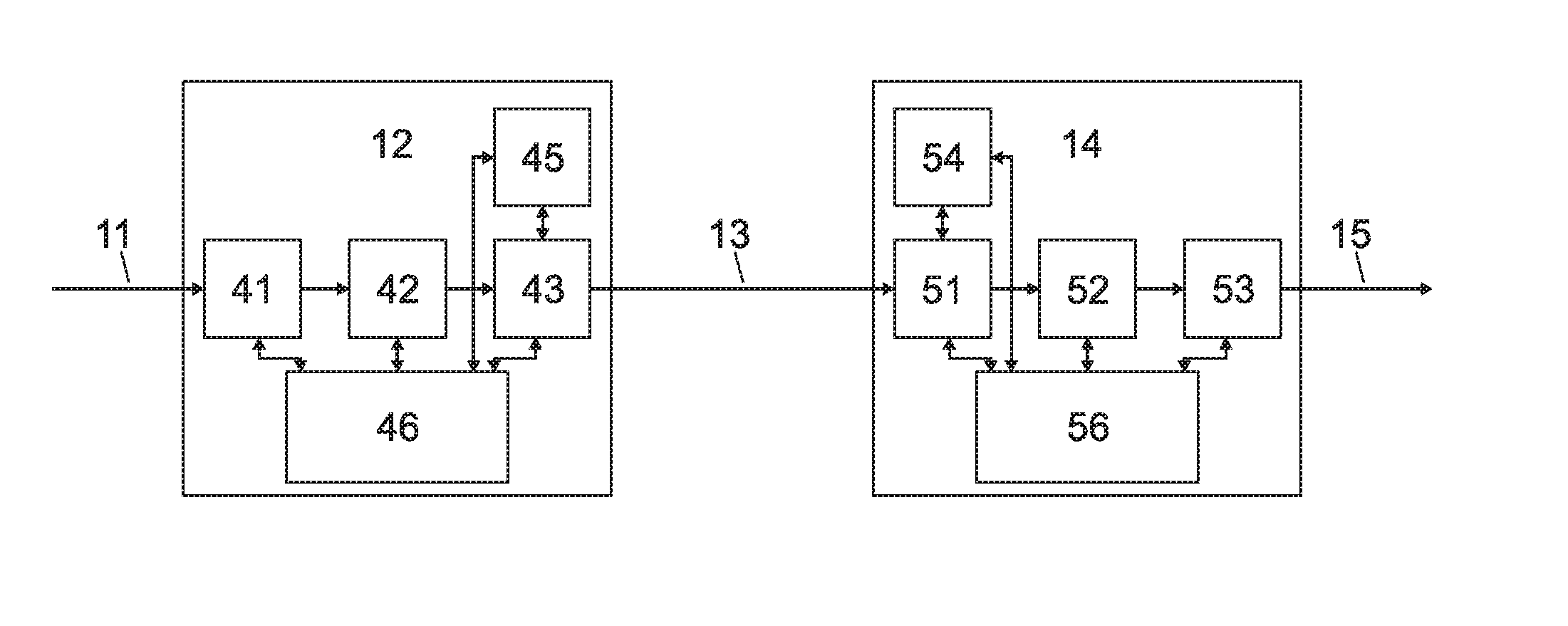
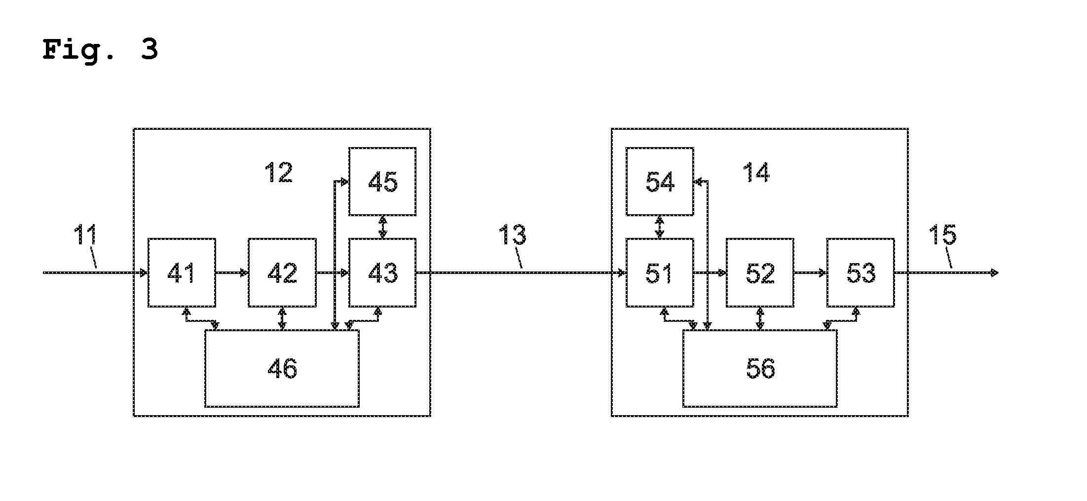
The invention is a device for transmitting digital signals between two parts of a computer tomograph that rotate relative to each other. The device uses a contactless data link with a transmitter and a receiver to maintain flexibility and different data rates over the same link. The device also includes a CDR to remove or minimize jitter, which is caused by electronic components and transmission lines. The device generates an internal stable clock with low jitter using a PLL and a frequency divider, which can be adjusted for different data rates and clock frequencies. The technical effect of the invention is improved flexibility and higher data transmission accuracy between the rotating and stationary parts of a computer tomograph.

Problems solved by technology

Typically in contactless data links the jitter is mainly deterministic, caused by bandwidth limiting of the electronic components as in the transmitter, the transmission line and the receiver.

Method used


Image

  • Rotating data transmission device
  • Rotating data transmission device
  • Rotating data transmission device

Examples


Embodiment Construction

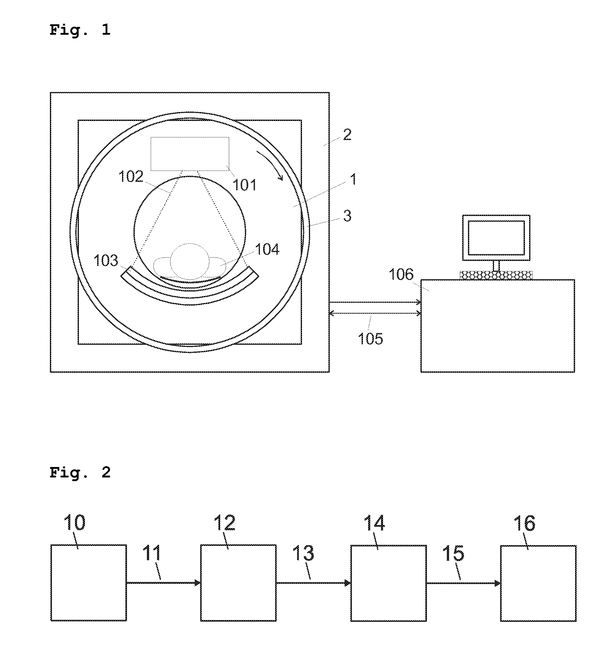
[0013]FIG. 1 shows by way of example a device in accordance with the invention. The computer tomograph (CT scanner) consists of two main mechanical components. A stationary part 2 serves as a basis and a support for the entire instrument, in which the rotating part 1 rotates. A patient 104 is positioned on a berth inside the opening of the rotating part. An X-ray tube 101 and a detector 103 disposed opposite thereto are provided for scanning the patient by means of X-rays 102. The X-ray tube 101 and the detector 103 are rotatably disposed on the rotating part 1. A rotating data transmission device 3 serves as an electrical connection between the rotating part 1 and the stationary part 2. With this, high electrical power for feeding the X-ray tube 101 is transmitted in a direction towards the rotating part 1, and at the same time video data are transmitted in the opposite direction by means of a high speed data link. A communication of control information in both directions is provid...


PUM


Abstract

A rotating data transmission device for computer tomographs, for transmission from a rotating part to a stationary part that is rotatably supported relative to the rotating part, comprises at least a rotating high-speed data transmitter unit, a rotating high-speed transmission line, a stationary high-speed data receiver unit. The rotating high-speed data transmitter unit contains a rotating pattern controller and the stationary high-speed data receiver unit contains a stationary data analyzer for analyzing patterns generated by the rotating pattern controller. Furthermore unit controllers are provided to control the units.

Description

PRIORITY CLAIM[0001]The present application claims priority to German Application No. 102005054981.0 filed Nov. 16, 2005.BACKGROUND OF THE INVENTION[0002]1. Field of the Invention[0003]The invention relates to a rotating data transmission device, in particular for use in computer tomographs. Here a transmission of digital image data obtained by an X-ray detector is effected in a non-contacting manner between a rotable gantry and a stationary part of a computer tomograph. Furthermore, data can also be transmitted in the opposite direction to control the rotable gantry.[0004]2. Description of the Prior Art[0005]A device for non-contacting rotating data transmission in computer tomographs is known from U.S. Pat. No. 5,530,422. In this, a signal to be transmitted is fed into a differentially operated strip conductor line on a rotating gantry, and is tapped off by a capacitive probe on the stationary part. Devices of this kind are usable up to data rates of an order of magnitude of appro...

Claims


Application Information

Patent Timeline
Patent Type & Authority Patents(United States)
IPC IPC(8): H01P1/00
CPCA61B6/032A61B6/56
Inventor KRUMME, NILSLINDORFER, STEPHANBERTL, ULRICHPOPESCU, STEFAN
Owner SCHLEIFRING & APPBAU
Learn More